Embedded computers and backplanes
VPX and RT2 serve rugged embedded computing for rail and industry; SYSOLC/SYTOLC stacks processor and I/O boards.


Rugged embedded computers and communication equipment move multi-gigabit data, RF and optical signals in enclosures that must pass EMC tests.
VPX connectors combine 6.25 Gbps differential, RF to 40 GHz and MT fiber modules; 38999-type fiber-optic hybrids and EMI filter connectors handle the enclosure wall; HJ30J and J7245 serve dense board-level links.
VPX differential modules at 100 Ω; RT2 is 10 Gbps capable
VPX VITA 67 RF modules, 50 Ω
J599 Series III π filter, 100 nF, at 100 MHz
J7245 Nano-D pitch, 9 to 69 contacts
VPX and RT2 serve rugged embedded computing for rail and industry; SYSOLC/SYTOLC stacks processor and I/O boards.
38999-type filter connectors stop EMI/RFI at the enclosure wall, fiber-optic hybrids carry optical and electrical circuits together, and J599A8 serves industrial networks and rail communication.
HJ30J carries compact differential links, J7245 dense board-to-cable links, and J29 rugged computers and control units.
VPX differential modules run 6.25 Gbps at 100 Ω; RT2 runs 6.25 Gbps, is 10 Gbps capable and holds 100 ± 15 Ω.
VITA 67 RF modules cover DC to 18 or 40 GHz at 50 Ω; VITA 66 fiber modules use MT ferrules with ≤ 1.5 dB insertion loss.
J599 Series III filter connectors offer C or π circuits from 75 pF to 100 nF, with up to 55 dB at 100 MHz.
The 38999-type fiber-optic hybrid mixes fiber with 50 Ω coax to 18 GHz and 1.65 Gbps differential contacts, at ≤ 0.6 dB optical loss for up to 4 fibers.
HJ30J uses a 1.27 mm pitch and J7245 Nano-D 0.635 mm; SYSOLC/SYTOLC fits 20 to 200 contacts at 6.35, 8, 10 or 12 mm board spacing.
J599A8 carries 2 to 32 fibers with ARINC 801 removable termini, at ≤ 0.6 dB multimode and ≤ 0.8 dB single-mode.
Swipe left or right to see all columns.
| Series | Data rate | Impedance or pitch | Current or power | Temperature | Datasheet |
|---|---|---|---|---|---|
| VPX | 6.25 Gbps differential | 100 Ω | 8 A per circuit, 48 V | −55 to +125 °C (−55 to +80 °C with fiber) | PDF, 213 KB |
| RT2 | 6.25 Gbps (10 Gbps capable) | 100 ± 15 Ω | 2.5 A power / 1 A signal | −55 to +125 °C | PDF, 180 KB |
| SYSOLC / SYTOLC | Up to 10 Gbps | 1.27 mm (0.635 mm pads) | 2.5 A | −55 to +125 °C | PDF, 211 KB |
| HJ30J | 1.65 Gbps (cable) / 3.125 Gbps (PCB to PCB) | 1.27 mm | 3 A | −55 to +125 °C | PDF, 193 KB |
Swipe left or right to see all columns.
| Series | Contact function | Loss or attenuation | Configuration | Temperature | Datasheet |
|---|---|---|---|---|---|
| J599 III fiber-optic | Fiber, power, coax, twinax and differential | ≤ 0.6 to ≤ 1 dB, by layout | 50 Ω, 0–18 GHz | −55 to +125 °C | PDF, 224 KB |
| J599 III filter | C or π | Up to 55 dB at 100 MHz | 75 pF to 100 nF | −55 to +125 °C | PDF, 247 KB |
| J599A8 | 2 to 32 fibers | ≤ 0.6 dB multimode / ≤ 0.8 dB single-mode | 9/125, 50/125, 62.5/125, OM3 | −55 to +125 °C | PDF, 233 KB |
Give the 3U or 6U format and the module at each position: differential, single-ended, power, RF or optical.
Give data rate, impedance, RF frequency and fiber type, and whether the link runs over cable or PCB.
Choose C or π circuits and a capacitance that puts the cut-off above your signal band.
Give board spacing, cable exit, temperature range, vibration and shock.
Send the module allocation, pin-out, fiber type and mounting drawing, and we will review your project.
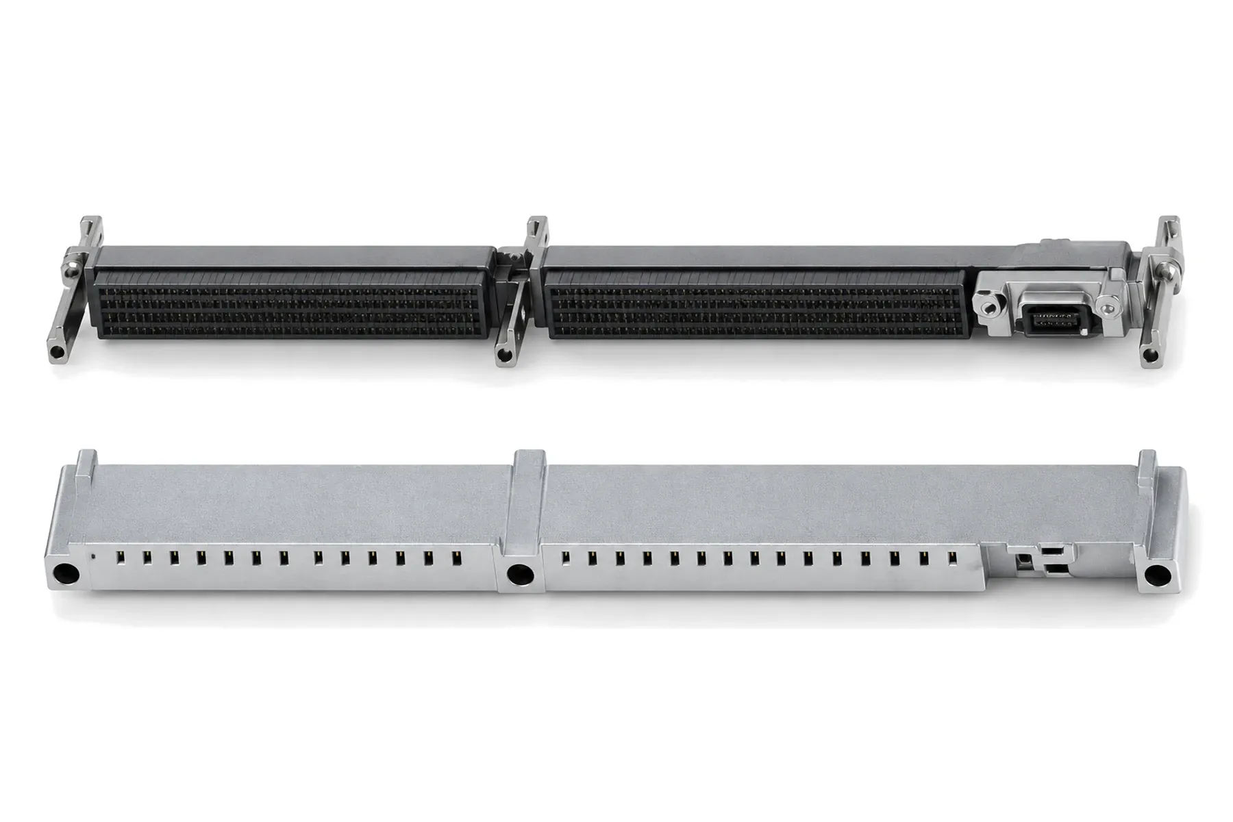
6.25 Gbps · RF to 40 GHz · MT fiber · 3U and 6U
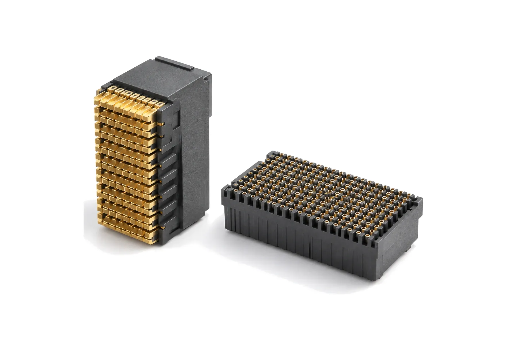
VITA 46 · 6.25 Gbps (to 10 Gbps) · press-fit
Fiber + power + coax + data in one 38999 shell · ≤ 0.6 dB
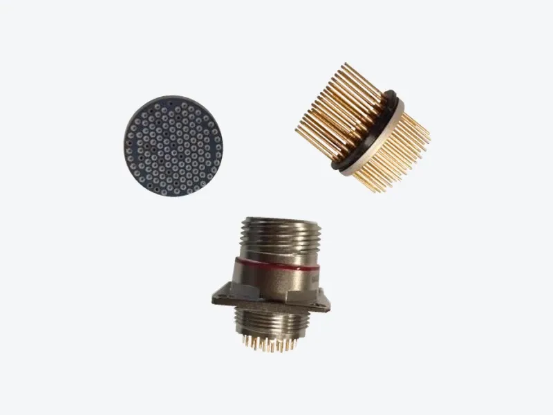
C or π filter per contact · up to 55 dB · marine grade
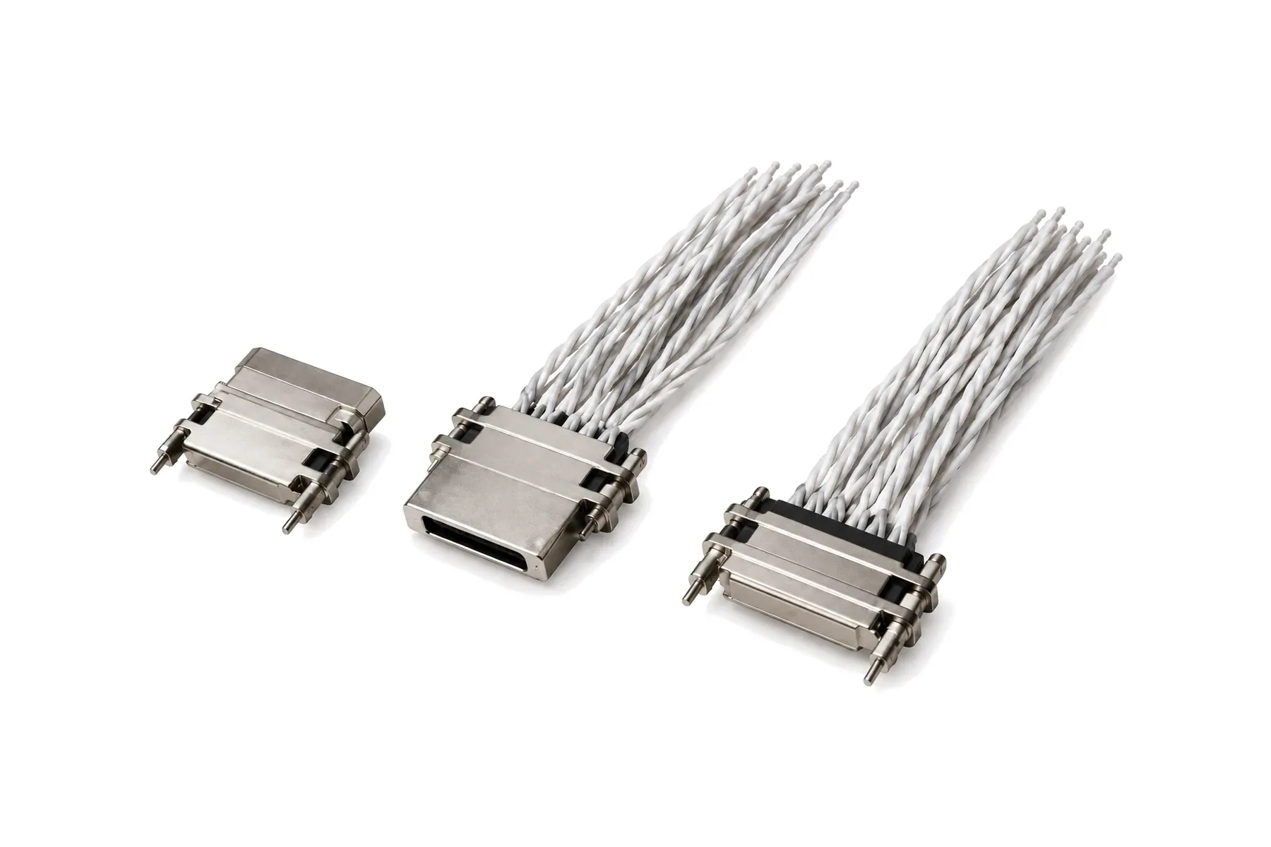
100 Ω differential pairs · up to 3.125 Gbps board-to-board
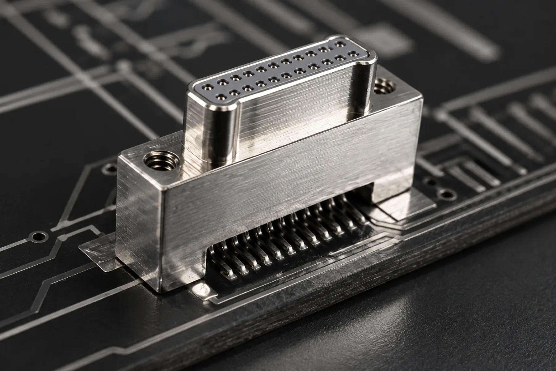
0.635 mm pitch · 9 to 69 contacts · metal shell
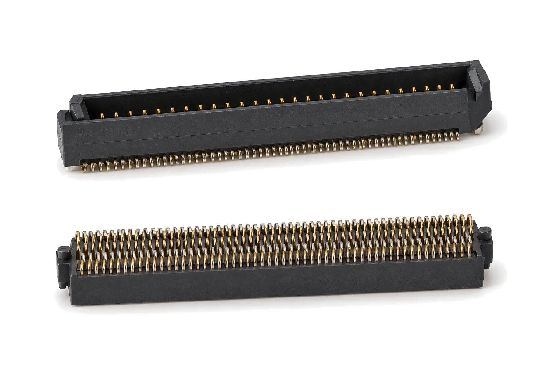
4-row SMT · 1.27 mm pitch · 20–200 contacts · to 10 Gbps
2 to 32 fibers · ≤ 0.6 dB multimode · ≤ 0.8 dB single-mode
All series can be customized — contact counts, cable lengths, materials and finishes.
An overview of VPX backplane connectors: VITA 46 differential modules, VITA 67 RF and VITA 66 fiber modules, 3U and 6U layouts, and how to specify them.
How EMI filter connectors work, C vs π filters, how to pick capacitance from cut-off frequency, and precautions for DC filter connectors.
Micro-D (1.27 mm pitch) vs Nano-D (0.635 mm pitch) connectors: differences in current, contact count, mating cycles and variants, and how to choose.
How 38999 insert arrangements are numbered, what contact sizes they use, and how service ratings M, N, I and II set the withstanding voltage.
VITA 46 covers the base VPX board format and differential backplane interface; VITA 66 covers optical modules and VITA 67 RF modules. Our VPX modules carry differential, single-ended, power, RF and optical signals for 3U and 6U boards.
VPX and RT2 run 6.25 Gbps differential, and RT2 is 10 Gbps capable at 100 ± 15 Ω. SYSOLC/SYTOLC board-to-board connectors run up to 10 Gbps.
Up to 55 dB at 100 MHz with the π 100 nF array. C and π circuits range from 75 pF to 100 nF; choose the value for your signal frequency.
≤ 0.6 dB with up to 4 fibers, ≤ 0.75 dB with more than 4, and ≤ 1 dB in hybrid layouts.
−55 to +125 °C, and −55 to +80 °C with fiber modules.
Part number, drawing, pin-out or a short description of your application.
Our engineers match the configuration and reply with a drawing and quotation.
Samples are built to order. The minimum order quantity is 10 pieces, and samples and production orders each take 4–8 weeks. Third-party testing to your specification is available on request.
You test the samples in your own equipment and approve them.
Production follows the approved sample configuration, with machining, molding, plating and assembly in our own Shenyang factory.
Send your part number, pin-out or drawing. Every inquiry is acknowledged by email within 1 business day, and an engineer follows up with a matched configuration, drawing or quotation.