VPX Rugged Hybrid Backplane Connectors (VITA 46 / 66 / 67)
6.25 Gbps · RF to 40 GHz · MT fiber · 3U and 6U
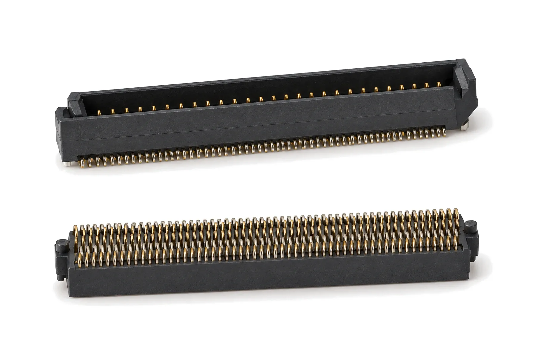
4-row SMT · 1.27 mm pitch · 20–200 contacts · to 10 Gbps
SYSOLC receptacles and SYTOLC plugs form a four-row surface-mount board-to-board pair for parallel boards. Contacts on a 1.27 mm pitch (0.635 mm staggered PCB pads) give 20 to 200 contacts in a low stack, for board spacings of 6.35, 8, 10 and 12 mm and data rates up to 10 Gbps.
| Parameter | Value | Condition |
|---|---|---|
| Rated current | 2.5 A | |
| Withstanding voltage | 550 V | |
| Contact resistance | ≤ 10 mΩ | |
| Insulation resistance | ≥ 1000 MΩ | |
| Data rate | Up to 10 Gbps |
| Parameter | Value | Condition |
|---|---|---|
| Durability | 100 mating cycles | |
| Board spacing | 6.35, 8, 10 or 12 mm | By plug style 02, 12, 22, 32 |
| Parameter | Value | Condition |
|---|---|---|
| Operating temperature | −55 to +125 °C |
Values not listed above — for example vibration level, leak rate or other environmental tests — can be tested to your requirements, including third-party testing. Specifications are subject to change; contact us for the current datasheet.
| Pins per row | Total contacts | Length A (mm) |
|---|---|---|
| 5 | 20 | 8.9 |
| 10 | 40 | 15.25 |
| 15 | 60 | 21.6 |
| 20 | 80 | 27.95 |
| 25 | 100 | 34.3 |
| 30 | 120 | 40.65 |
| 35 | 140 | 47 |
| 40 | 160 | 53.35 |
| 45 | 180 | 59.7 |
| 50 | 200 | 66.05 |
| Series code | Version | Notes |
|---|---|---|
| SYSOLC | Four-row SMT receptacle | |
| SYTOLC | Four-row SMT plug | Styles 02, 12, 22, 32 set the stack height |
SYSOLC-1[pins per row]-02-[plating]-Q-[guide] / SYTOLC-1-[pins per row]-[style]-[plating]-Q-[guide]
Example: SYSOLC-150-02-G-Q-A — Receptacle, 50 contacts per row (200 total), 1.27 µm gold, guide pins
| Code segment | Options |
|---|---|
| Pins per row | |
| Plug style | |
| Plating | |
| Guide |
6.35, 8, 10 or 12 mm, set by the SYTOLC plug style. Other stack heights can be reviewed per project.
Part number, drawing, pin-out or a short description of your application.
Our engineers match the configuration and reply with a drawing and quotation.
Samples are made to your order. Third-party testing to your specification is available on request.
You test the samples in your own equipment and approve them.
Production follows the approved sample configuration.
Send your part number, pin-out or drawing. An engineer will reply by email.
6.25 Gbps · RF to 40 GHz · MT fiber · 3U and 6U
VITA 46 · 6.25 Gbps (to 10 Gbps) · press-fit
45–240 contacts · wire-spring sockets · 1000 cycles