Working with us · Updated 2026-11-03
How to Identify a Connector from Photos
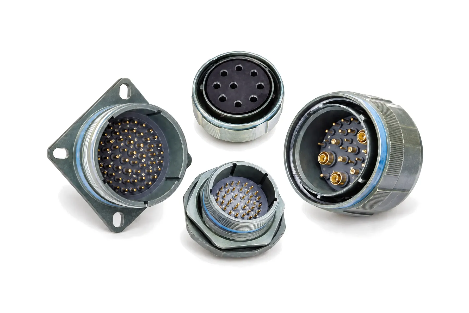
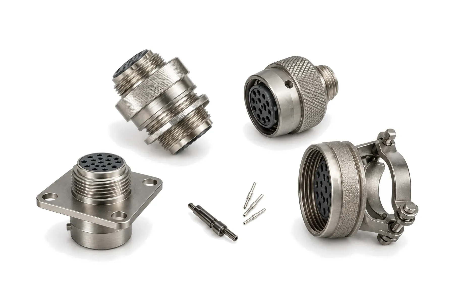
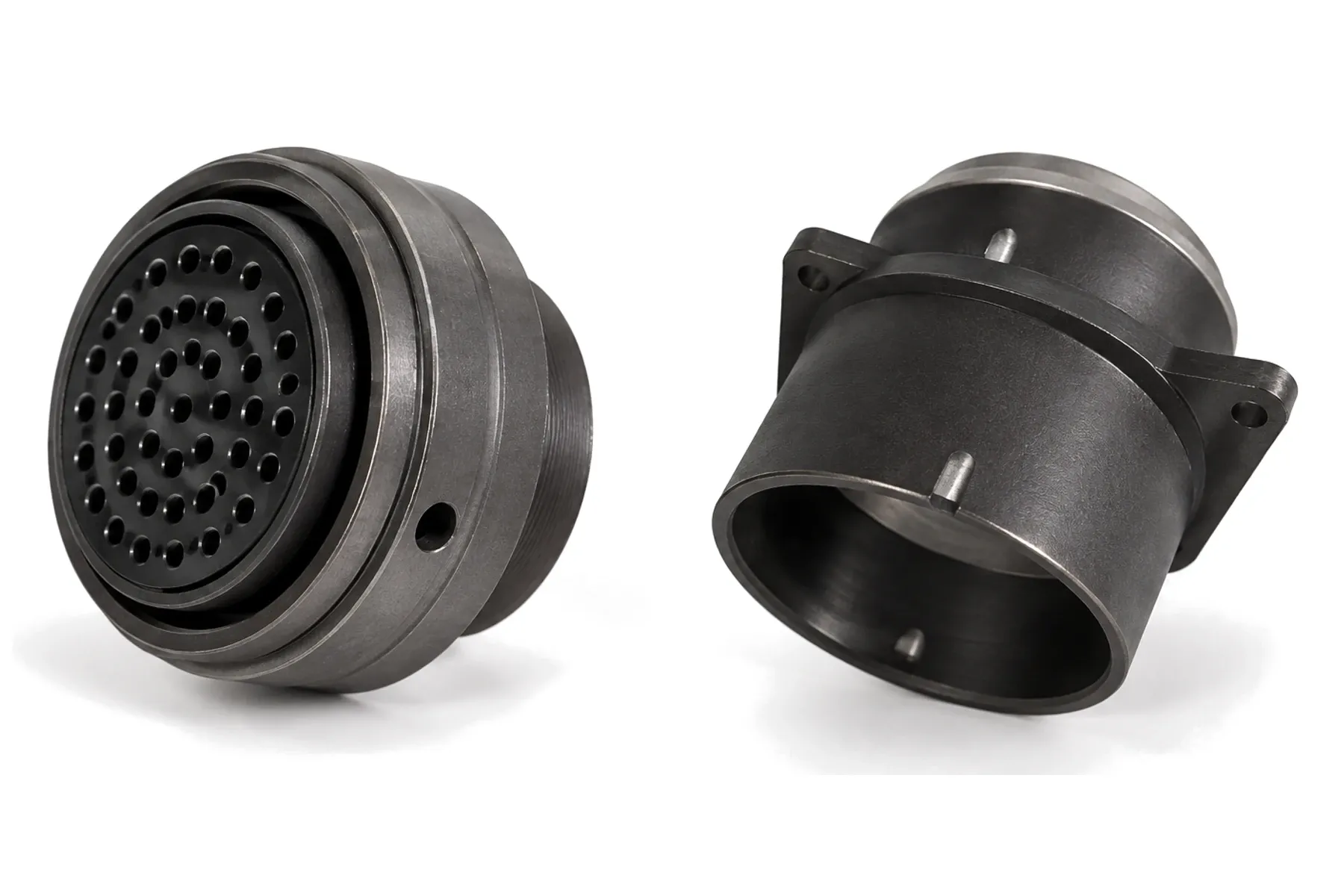
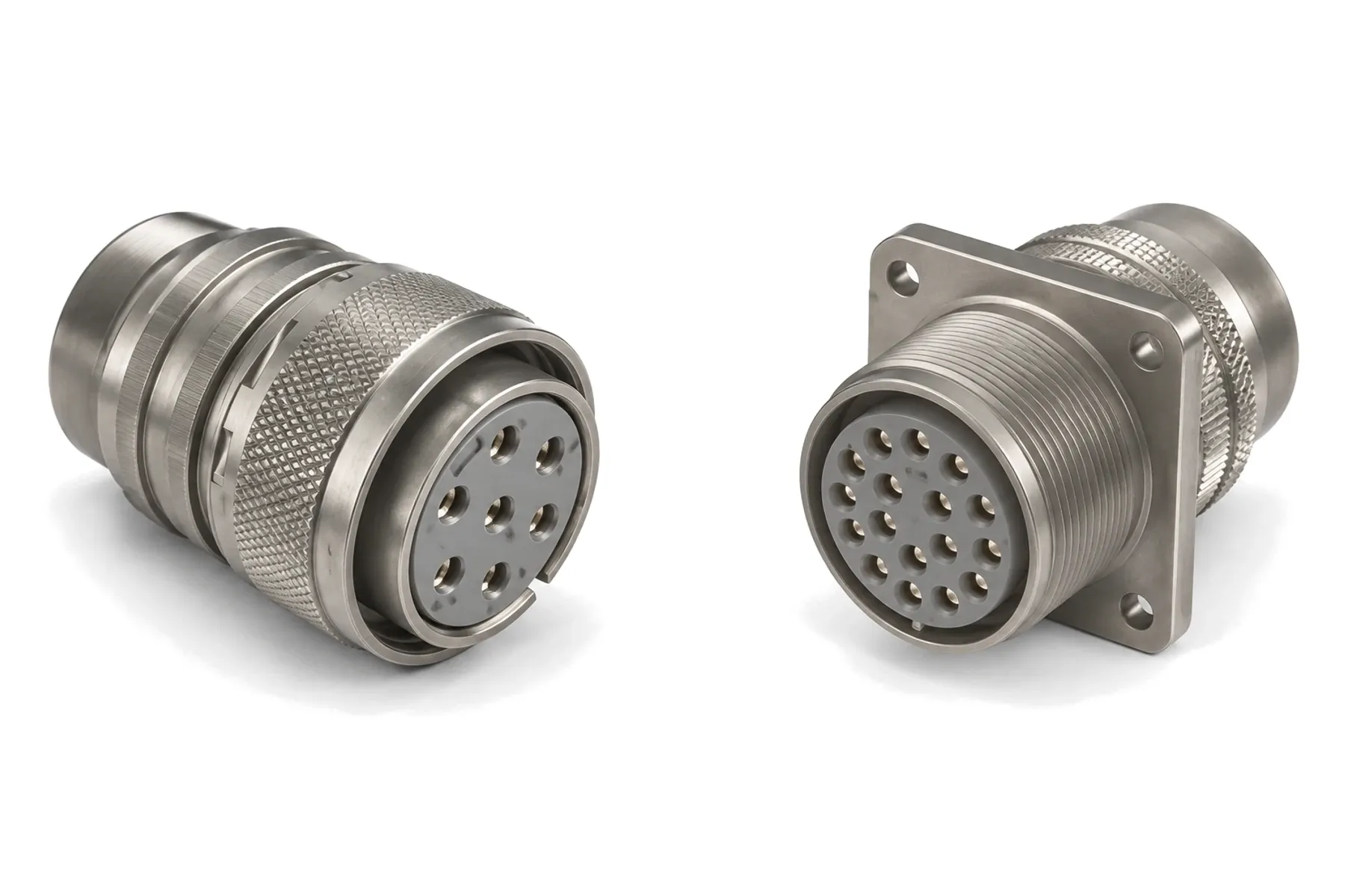
The marking has worn off, the drawing lists a part that is no longer made, or the supplier quotes a lead time you cannot accept. If you have the connector, or a good photo of it, the part number is often not needed. From the coupling, contact layout, keying and mounting, an engineer can read most of what the part number would say.
This guide shows which photos to take, what to measure, and what each detail tells us. Send the result with your quote request; we reply with a corresponding configuration and build samples for your mating test.
Six photos that identify most connectors
Take the photos in daylight or under even light, without flash; flash reflects off gold contacts and hides the layout. Put the connector on a plain background and fill the frame.
- Mating face, straight on. The most important photo. It shows the number of contacts, their sizes and positions, the keys or keyways and, on most military-type inserts, the small letters or numbers next to each contact cavity.
- Side view. Shows how it couples (thread, bayonet, push-pull or breech lock), the length of the shell and any coupling ring or nut.
- Rear. Shows how wires are terminated: crimp contacts in a rubber grommet, solder cups, PCB pins, potting or a molded cable.
- Mounting. Square flange with four holes, single jam nut, cable plug, or a body that is welded or soldered into a bulkhead or housing.
- Markings, close up. Any characters on the shell, flange, coupling nut or insert, even if only partly readable. A manufacturer code, a fragment of the part number or a date code narrows the search. Note the shell colour and finish too (olive drab, nickel, black, bare stainless), since indoor light can make them look alike.
- The mating half, if you have it, from the same angles.
Lay a ruler or caliper beside the connector in photos 1, 2 and 4, so we can scale the picture.
Measurements worth adding
- Diameter of the mating thread or bayonet barrel on the receptacle, or the inside of the plug coupling nut. The outside of a knurled nut varies between makers, so it says less about the shell size;
- Shell length, and the rear accessory thread and cable diameter if the connector must fit an existing backshell or cable;
- Flange size and hole spacing for flange receptacles, or the panel cut-out;
- Contact spacing for rectangular connectors: measure across several contacts in a row and divide by the number of gaps.
Calipers are better than a ruler. Write down whether you measured in millimetres or inches.
What the details tell us
Coupling
| What you see | Usually points to |
|---|---|
| Coupling nut that threads on in about one turn and clicks against a ratchet | 38999 Series III type (J599 Series III) |
| Bayonet pins on the receptacle, long shell around the contacts | 38999 Series I type (GJB599 Series I) |
| Bayonet coupling, shorter and lighter shell | 38999 Series II type, or a 26482 type |
| Quarter-turn coupling ring with a breech lock | 38999 Series IV type |
| Large threaded or reverse-bayonet shell, often with heavy contacts | MIL-DTL-5015 type |
| Sleeve that latches when pushed and releases when pulled | Push-pull connector |
The four 38999 series do not mate with each other, so identifying the coupling is the first step. See 38999 Series I, II, III and IV for the differences.
Contact layout
Count the contacts and note how many sizes there are; larger contacts have larger holes in the insert. Together with the shell size, the count and the pattern usually identify the insert arrangement. For example, a 38999 shell size 25 with 128 small contacts is arrangement 25-35. The letters or numbers molded next to the cavities help confirm it.
Note also whether the connector has pins or sockets. Either half can carry either contact type, so a plug is not always the pin side.
Keying
38999-type connectors have one wide master key and smaller keys. The angle of the small keys relative to the master key sets the key position (N, A, B, C, D or E), which stops identical connectors on one panel from being cross-mated. A straight-on photo of the mating face is enough to read it; if the keys are hard to see, mark the master key with a pen before taking the photo. 26482 and 5015 types key differently: alternate positions, marked with letters such as W, rotate the insert relative to the master key.
Rectangular connectors
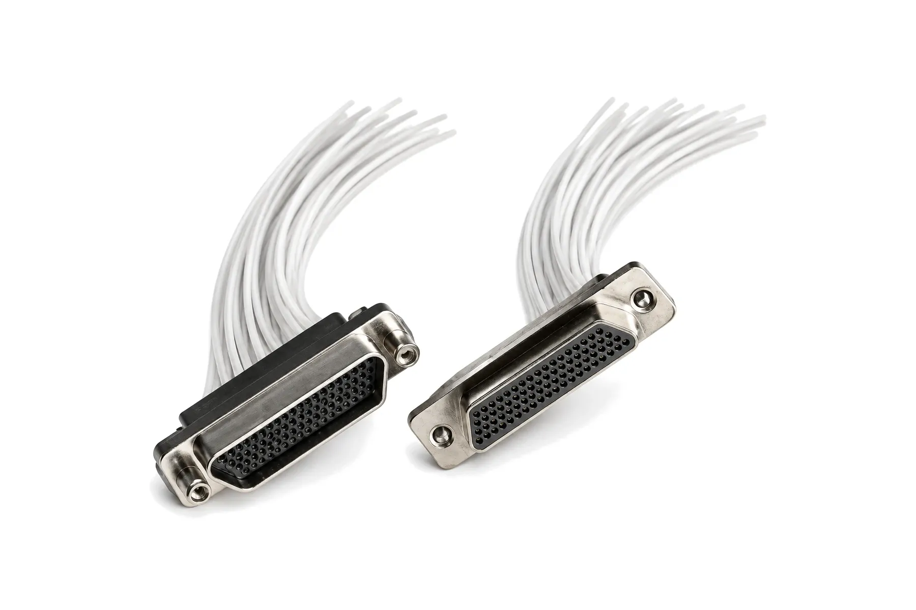
For D-shaped metal shells, the contact spacing separates the families:
| Contact spacing | Type |
|---|---|
| 2.77 mm (0.109 in) | Standard D-sub |
| 1.27 mm (0.050 in) | Micro-D, MIL-DTL-83513 type |
| 0.635 mm (0.025 in) | Nano-D, MIL-DTL-32139 type |
Then count the contacts and check whether the rear has wire pigtails, solder cups or PCB pins. See Micro-D vs Nano-D.
Hermetic receptacles
Look at the rear. If each pin sits in a glass bead or a solid glass insert and ends in a solder cup or a straight pin, it is a glass-sealed receptacle; a black or grey compound around the pins means a potted or epoxy construction. Note whether the body has a flange, a jam nut or a plain ring for welding or soldering into a wall. The glass-to-metal vs epoxy guide explains the difference.
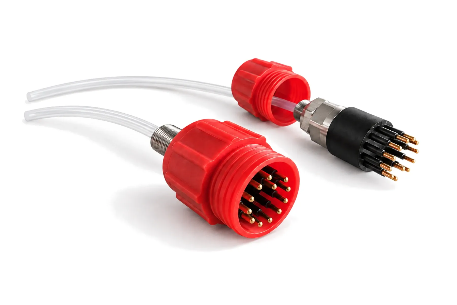
Subsea connectors
Tell us whether the body is molded rubber or a metal shell, how many contacts it has, and the depth it works at. A photo of the cable entry and any locking sleeve helps. See rubber-molded vs metal-shell underwater connectors.
What to write with the photos
- Quantity, and whether you need plugs, receptacles or both;
- details or markings of the mating half, if it stays installed on the equipment;
- the application: temperature, vibration, immersion depth or sealing needs, current and voltage;
- the wire size and cable, if you need an assembly rather than a connector.
What happens next
Our engineers compare the coupling, layout, keying and dimensions with our catalog. If a detail is unclear, we ask for one more photo or measurement rather than guess. You then receive the corresponding configuration and a quotation. Samples are built for your mating test before production; samples and production each take 4–8 weeks, from 10 pieces. If nothing in the catalog matches, we can propose a custom connector.
The quote request form takes up to three files, compressed automatically: send the mating face, the side view and the markings there. Full-resolution close-ups and the other photos can follow by email after we reply. We confirm receipt within one business day.