
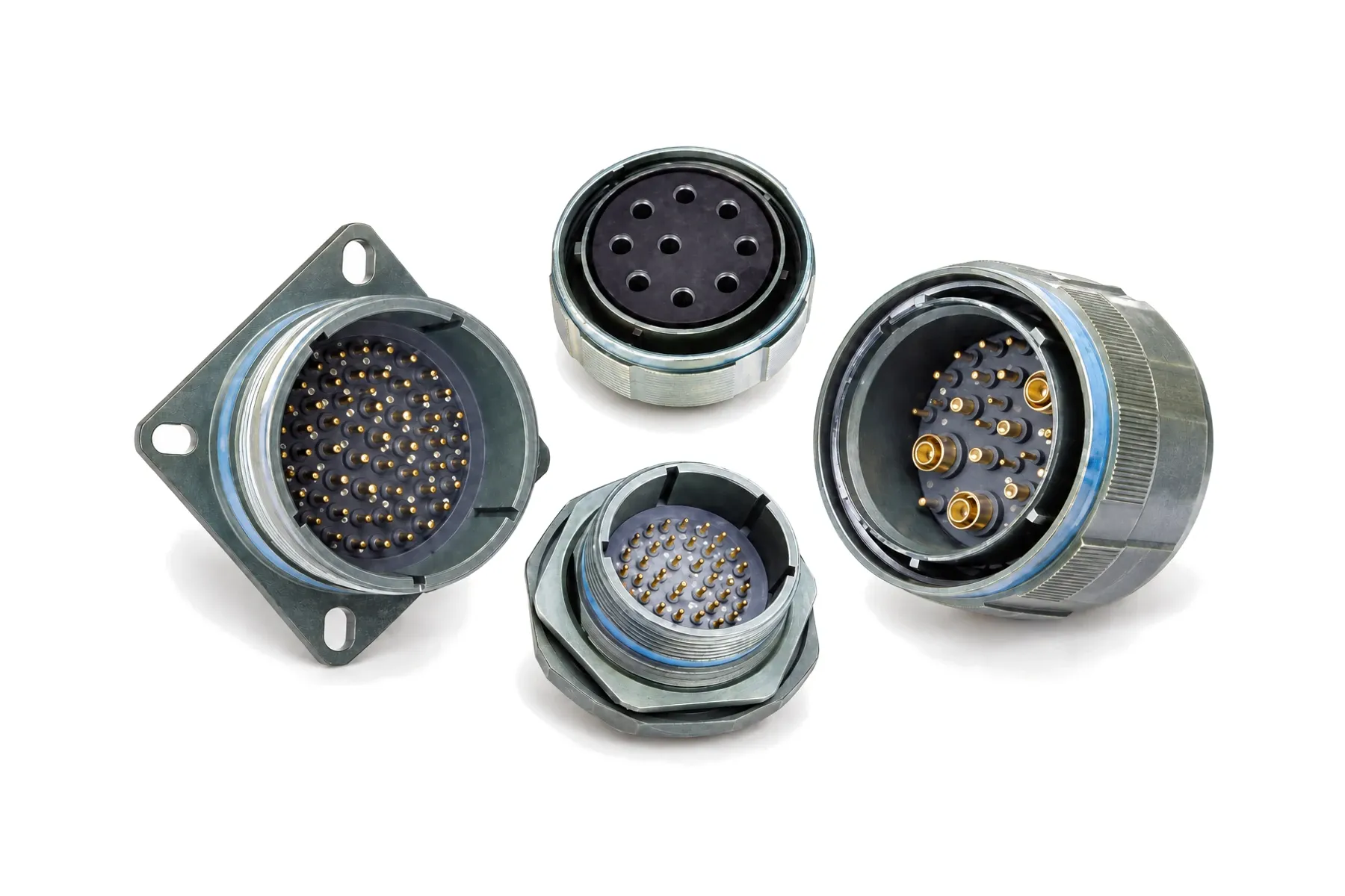
J599/20 Square-Flange Receptacles, D38999/20-Type
The J599/20 is the wall-mount receptacle of our J599 Series III family: a square flange screwed to the equipment panel, with removable crimp contacts.
- Mounting
- Square flange (wall mount)
- Insert arrangements
- 184
- Contacts
- Crimp pin (P) or socket (S), sizes 26 to 10
- Shell materials
- Aluminum, stainless steel, composite, titanium
J599/20 is the square-flange receptacle in our J599 Series III range, built to GJB 599B Series III. The flange is screwed to the equipment panel, so it carries mating and cable loads through the fixing screws and the flange face. It mates with the J599/26 plug through a triple-start threaded coupling.
Because the contacts are crimp and removable, the receptacle is wired as a harness and fitted to the panel afterwards. The same J599/20 shell is the base for the double-flange PCB receptacles (-D17 / -E17) and, with C contacts, for the hermetic feed-through receptacle J599/20…C.
When to choose this style
- Your panel has room for a flange and fixing screws, and you want the receptacle located against rotation by the flange itself.
- You wire the receptacle to a harness with crimp contacts, not to a sealed housing (for a sealed housing, see the hermetic J599/21).
- You want the same footprint for a crimp version now and a PCB double-flange version (J599/20-D17 / -E17) later.
- Your equipment is exposed to sea air: choose stainless (K), titanium (TA) or composite, or the marine-environment M version, for example J599/20MKB35PN.
- Several receptacles of the same size and layout sit on one panel: give each a different key position (N, A–E).
Ordering example
J599/20KJ61PA
| Segment | Code | Meaning |
|---|---|---|
| Type | 20 | Square-flange receptacle |
| Class | (none) | Standard |
| Finish | K | Stainless steel, passivated |
| Shell | J | Shell size 25 |
| Arrangement | 61 | Layout 25-61: 61 × size 20 contacts |
| Contact | P | Pin (crimp) |
| Key | A | Alternate key position A |
Mating plug: J599/26KJ61SA (same finish, shell, layout and key; socket contacts).
Finish K: shell-to-shell conductivity 10 mΩ, shielding 45 dB at 10 GHz, −65 to +200 °C, 500 h salt spray. For the highest shielding choose F (aluminum, nickel) or S (stainless, nickel): ≥ 65 dB at 10 GHz and ≥ 85 dB at 1 GHz.
Dimensions (mm)
| Shell sizes | Code | Amax | Bmax | Cmax | D | H | L | L1 | L2 |
|---|---|---|---|---|---|---|---|---|---|
| 9 | A | 20.83 | 2.5 | 15.88 | M12×1-6g | 3.25 | 23.8 | 15.09 | 18.26 |
| 11 | B | 20.83 | 2.5 | 19.05 | M15×1-6g | 3.25 | 26.2 | 18.26 | 20.62 |
| 13 | C | 20.83 | 2.5 | 22.23 | M18×1-6g | 3.25 | 28.6 | 20.62 | 23.01 |
| 15 | D | 20.83 | 2.5 | 25.4 | M22×1-6g | 3.25 | 31 | 23.01 | 24.61 |
| 17 | E | 20.83 | 2.5 | 30.16 | M25×1-6g | 3.25 | 33.3 | 24.61 | 26.97 |
| 19 | F | 20.83 | 2.5 | 31.75 | M28×1-6g | 3.25 | 36.5 | 26.97 | 29.36 |
| 21 | G | 20.07 | 3.2 | 34.73 | M31×1-6g | 3.25 | 39.7 | 29.36 | 31.75 |
| 23 | H | 20.07 | 3.2 | 38.1 | M34×1-6g | 3.91 | 42.9 | 31.75 | 34.93 |
| 25 | J | 20.07 | 3.2 | 41.28 | M37×1-6g | 3.91 | 46 | 34.93 | 38.1 |
| Shell sizes | Code | Amax | Bmax | Cmax | D | H | L | L1 | L2 |
|---|---|---|---|---|---|---|---|---|---|
| 9 | A | 18.95 | 2.5 | 15.88 | M12×1-6g | 3.25 | 23.8 | 15.09 | 18.26 |
| 11 | B | 18.95 | 2.5 | 19.05 | M15×1-6g | 3.25 | 26.2 | 18.26 | 20.62 |
| 13 | C | 18.95 | 2.5 | 22.23 | M18×1-6g | 3.25 | 28.6 | 20.62 | 23.01 |
| 15 | D | 18.95 | 2.5 | 25.4 | M22×1-6g | 3.25 | 31 | 23.01 | 24.61 |
| 17 | E | 18.95 | 2.5 | 30.16 | M25×1-6g | 3.25 | 33.3 | 24.61 | 26.97 |
| 19 | F | 18.95 | 2.5 | 31.75 | M28×1-6g | 3.25 | 36.5 | 26.97 | 29.36 |
| 21 | G | 18.95 | 3.2 | 34.73 | M31×1-6g | 3.25 | 39.7 | 29.36 | 31.75 |
| 23 | H | 18.95 | 3.2 | 38.1 | M34×1-6g | 3.91 | 42.9 | 31.75 | 34.93 |
| 25 | J | 18.95 | 3.2 | 41.28 | M37×1-6g | 3.91 | 46 | 34.93 | 38.1 |
| Shell sizes | Code | Amax | Bmax | Cmax | D | H | L | L1 | L2 |
|---|---|---|---|---|---|---|---|---|---|
| 9 | A | 19.75 | 3.65 | 15.88 | M12×1-6g | 3.25 | 23.8 | 18.26 | 15.09 |
| 11 | B | 19.75 | 3.65 | 19.05 | M15×1-6g | 3.25 | 26.2 | 20.62 | 18.26 |
| 13 | C | 19.75 | 3.65 | 22.23 | M18×1-6g | 3.25 | 28.6 | 23.01 | 20.62 |
| 15 | D | 19.75 | 3.65 | 25.4 | M22×1-6g | 3.25 | 31 | 24.61 | 23.01 |
| 17 | E | 19.75 | 3.65 | 30.16 | M25×1-6g | 3.25 | 33.3 | 26.97 | 24.61 |
| 19 | F | 19.75 | 3.65 | 31.75 | M28×1-6g | 3.25 | 36.5 | 29.36 | 26.97 |
| 21 | G | 18.95 | 4.35 | 34.9 | M31×1-6g | 3.25 | 39.7 | 31.75 | 29.36 |
| 23 | H | 18.95 | 4.35 | 38.1 | M34×1-6g | 3.91 | 42.9 | 34.93 | 31.75 |
| 25 | J | 18.95 | 4.35 | 41.28 | M37×1-6g | 3.91 | 46 | 38.1 | 34.93 |
Panel cut-out (mm)
| Shell sizes | Code | A | B min | C |
|---|---|---|---|---|
| 9 | A | 18.26 | 16.66 | 3.25 |
| 11 | B | 20.62 | 20.22 | 3.25 |
| 13 | C | 23.01 | 23.42 | 3.25 |
| 15 | D | 24.61 | 26.59 | 3.25 |
| 17 | E | 26.97 | 30.96 | 3.25 |
| 19 | F | 29.36 | 32.94 | 3.25 |
| 21 | G | 31.75 | 36.12 | 3.25 |
| 23 | H | 34.93 | 39.29 | 3.91 |
| 25 | J | 38.10 | 42.47 | 3.91 |
| Shell sizes | Code | A | D min | C |
|---|---|---|---|---|
| 9 | A | 18.26 | 13.11 | 3.25 |
| 11 | B | 20.62 | 15.88 | 3.25 |
| 13 | C | 23.01 | 19.05 | 3.25 |
| 15 | D | 24.61 | 23.01 | 3.25 |
| 17 | E | 26.97 | 25.81 | 3.25 |
| 19 | F | 29.36 | 28.98 | 3.25 |
| 21 | G | 31.75 | 32.16 | 3.25 |
| 23 | H | 34.93 | 34.93 | 3.91 |
| 25 | J | 38.10 | 37.69 | 3.91 |
Frequently asked questions
Do you make D38999/20 receptacles?
We make the J599/20, a D38999/20-Type square-flange receptacle built to GJB 599B Series III. Send us your D38999 part number; we will propose the matching configuration and samples for your own mating test.
Which finish should I choose for a wall-mount receptacle?
Nickel on aluminum (F) is the general choice. For marine or corrosive locations choose composite (M, 2000 h salt spray), stainless steel or titanium (TA). Cadmium finishes (W, J) are not RoHS compliant and are supplied on request.
Is there a version that also mounts to a circuit board?
Yes. J599/20-D17 (M3 threaded inserts) and J599/20-E17 (M3 threaded holes) are double-flange receptacles that fix to the panel and the PCB at the same time, so the board carries no connector loads. Both mate with J599/26 plugs.
What protects the receptacle when it is unmated?
A J599/33 receptacle cap in the same material and finish as the shell, with a stainless cable, steel wire rope or nylon cord lanyard. Caps are ordered separately.
Can you change the layout or contacts?
Yes. Contact count, contact sizes and materials can be customized. Send your drawing or part number; we will acknowledge your inquiry by email within 1 business day.