
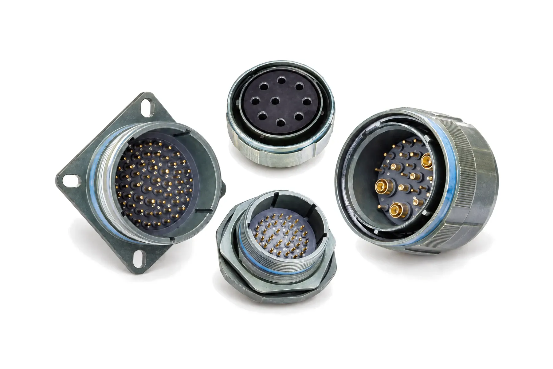
Hermetic J599 Series III Receptacles, MIL-DTL-38999 Series III Type
Hermetic J599 Series III receptacles seal a pressure or vacuum boundary in four mounting styles, with solder-sealed pin contacts and a leak rate of ≤ 1 × 10⁻⁸ Pa·m³/s.
- Leak rate
- ≤ 1 × 10⁻⁸ Pa·m³/s at 0.1 MPa differential
- Mounting
- Square flange (/21), jam nut (/23), solder mount (/25), weld mount (/27)
- Contacts
- Solder-sealed pin (P); feed-through pin (C, C8 extended)
- Shell
- Stainless steel (Y electropolished, N nickel) or titanium
Our hermetic receptacles use the J599 Series III interface and the triple-start threaded coupling, so they mate with the J599/26 plug. Each receptacle has solder-sealed pin contacts and is rated at a leak rate of ≤ 1 × 10⁻⁸ Pa·m³/s at 0.1 MPa pressure differential. Shells are stainless steel or titanium.
Choose the mounting style by how the receptacle joins the housing. J599/21 (square flange) and J599/23 (jam nut) fit a panel in the same way as the crimp J599/20 and /24. J599/25 is soldered into the housing and J599/27 is welded in. Where a cable must pass a sealed wall and stay pluggable on both sides, the feed-through receptacles J599/20…C and J599/24…C take a standard plug on one side and a -U plug on the other.
When to choose this style
- A sealed enclosure, pressure vessel or vacuum chamber needs a pluggable electrical interface at the wall.
- The housing is metal and you want a permanent joint: solder mount (/25) or weld mount (/27), no gasket at the panel.
- You want to keep a bolted or nut-clamped panel joint: square flange (/21) or jam nut (/23).
- The wall is a bulkhead between two cabled zones: feed-through J599/20…C or /24…C, with C8 for extended contacts.
- The housing is in an exposed marine location: the M version includes hermetic and bulkhead feed-through receptacles in stainless steel or titanium.
Ordering example
J599/21YD19PN
| Segment | Code | Meaning |
|---|---|---|
| Type | 21 | Hermetic receptacle, square flange |
| Class | (none) | Standard |
| Finish | Y | Stainless steel hermetic, electropolished |
| Shell | D | Shell size 15 |
| Arrangement | 19 | Layout 15-19: 19 × size 20 contacts |
| Contact | P | Solder-sealed pin (hermetic receptacles) |
| Key | N | Normal key position |
Other mounting styles: replace 21 with 23 (jam nut), 25 (solder mount) or 27 (weld mount). Finish Y: shell-to-shell conductivity 10 mΩ, 45 dB at 10 GHz, −65 to +200 °C, 500 h salt spray.
Feed-through: type 20 or 24 with contact code C (C8 for extended contacts), mated by a J599/26 plug on the front and a J599/26…-U plug on the rear. Send the layout and both mating plugs; we will confirm the complete feed-through part number.
Dimensions (mm)
| Shell sizes | Code | A | L1 | L2 | L3 | H |
|---|---|---|---|---|---|---|
| 9 | A | 15.83 | 15.09 | 18.26 | 23.8 | 3.25 |
| 11 | B | 19.01 | 18.26 | 20.62 | 26.2 | 3.25 |
| 13 | C | 22.18 | 20.62 | 23.01 | 28.6 | 3.25 |
| 15 | D | 25.36 | 23.01 | 24.61 | 31 | 3.25 |
| 17 | E | 30.11 | 24.61 | 26.97 | 33.3 | 3.25 |
| 19 | F | 31.69 | 26.97 | 29.36 | 36.5 | 3.25 |
| 21 | G | 34.87 | 29.36 | 31.75 | 39.7 | 3.25 |
| 23 | H | 38.04 | 31.75 | 34.93 | 42.9 | 3.91 |
| 25 | J | 41.22 | 34.93 | 38.1 | 46 | 3.91 |
| Shell sizes | Code | A | B | C | L | L1 | L2 | W |
|---|---|---|---|---|---|---|---|---|
| 9 | A | 16.3 | 30.2 | M17×1-6g | 29.2 | 27 | 16.53 | 2.6 |
| 11 | B | 19.4 | 34.9 | M20×1-6g | 29.2 | 31.8 | 19.07 | 2.6 |
| 13 | C | 22.7 | 38.1 | M25×1-6g | 29.3 | 34.9 | 23.82 | 2.6 |
| 15 | D | 25.9 | 41.3 | M28×1-6g | 29.3 | 38.1 | 26.97 | 2.6 |
| 17 | E | 29 | 44.5 | M32×1-6g | 29.3 | 41.3 | 30.15 | 2.6 |
| 19 | F | 32.2 | 49.2 | M35×1-6g | 30.1 | 46 | 33.32 | 3.4 |
| 21 | G | 35.4 | 52.4 | M38×1-6g | 30.1 | 49.2 | 36.5 | 3.4 |
| 23 | H | 38.6 | 55.6 | M41×1-6g | 30.1 | 52.4 | 39.67 | 3.4 |
| 25 | J | 41.7 | 58.7 | M44×1-6g | 30.1 | 55.6 | 42.85 | 3.4 |
| Shell sizes | Code | A | B | C | L |
|---|---|---|---|---|---|
| 9 | A | 15.83 | 16.8 | 19.4 | 22.5 |
| 11 | B | 19.01 | 19.6 | 21.8 | 22.5 |
| 13 | C | 22.18 | 22.8 | 24.9 | 22.5 |
| 15 | D | 25.36 | 25.9 | 28.1 | 22.5 |
| 17 | E | 30.11 | 29.1 | 31.3 | 22.5 |
| 19 | F | 31.69 | 31.5 | 33.6 | 22.5 |
| 21 | G | 34.87 | 34.7 | 36.8 | 22.5 |
| 23 | H | 38.04 | 37.9 | 40 | 23.3 |
| 25 | J | 41.22 | 41 | 43.2 | 23.3 |
| Shell sizes | Code | A | B | C | W |
|---|---|---|---|---|---|
| 9 | A | 15.83 | 23.9 | 24.7 | 3.2 |
| 11 | B | 19.01 | 27 | 27.8 | 3.2 |
| 13 | C | 22.18 | 30.2 | 31 | 3.2 |
| 15 | D | 25.36 | 33.4 | 34.2 | 3.2 |
| 17 | E | 30.11 | 35.6 | 36.4 | 3.2 |
| 19 | F | 31.69 | 39.3 | 40.1 | 3.2 |
| 21 | G | 34.87 | 42.9 | 43.7 | 3.2 |
| 23 | H | 38.04 | 47.1 | 47.9 | 4.0 |
| 25 | J | 41.22 | 49.3 | 50.1 | 4.0 |
| Shell sizes | Code | A | L1 | L2 | L3 | H | W |
|---|---|---|---|---|---|---|---|
| 9 | A | 15.88 | 15.09 | 18.26 | 23.8 | 3.25 | 2.5 |
| 11 | B | 19.05 | 18.26 | 20.62 | 26.2 | 3.25 | 2.5 |
| 13 | C | 22.23 | 20.62 | 23.01 | 28.6 | 3.25 | 2.5 |
| 15 | D | 25.4 | 23.01 | 24.61 | 31 | 3.25 | 2.5 |
| 17 | E | 30.16 | 24.61 | 26.97 | 33.3 | 3.25 | 2.5 |
| 19 | F | 31.75 | 26.97 | 29.36 | 36.5 | 3.25 | 2.5 |
| 21 | G | 34.73 | 29.36 | 31.75 | 39.7 | 3.25 | 3.2 |
| 23 | H | 38.1 | 31.75 | 34.93 | 42.9 | 3.91 | 3.2 |
| 25 | J | 41.28 | 34.93 | 38.1 | 46 | 3.91 | 3.2 |
| Shell sizes | Code | A | B | L1 | L2 | W |
|---|---|---|---|---|---|---|
| 9 | A | M17×1-6g | 30.2 | 27 | 16.53 | 2.5 |
| 11 | B | M20×1-6g | 34.9 | 31.8 | 19.07 | 2.5 |
| 13 | C | M25×1-6g | 38.1 | 34.9 | 23.82 | 2.5 |
| 15 | D | M28×1-6g | 41.3 | 38.1 | 26.97 | 2.5 |
| 17 | E | M32×1-6g | 44.5 | 41.3 | 30.15 | 2.5 |
| 19 | F | M35×1-6g | 49.2 | 46 | 33.32 | 2.5 |
| 21 | G | M38×1-6g | 52.4 | 49.2 | 36.5 | 3.2 |
| 23 | H | M41×1-6g | 55.6 | 52.4 | 39.67 | 3.2 |
| 25 | J | M44×1-6g | 58.7 | 55.6 | 42.85 | 3.2 |
Panel cut-out (mm)
| Shell sizes | Code | A | B min | C |
|---|---|---|---|---|
| 9 | A | 18.26 | 16.66 | 3.25 |
| 11 | B | 20.62 | 20.22 | 3.25 |
| 13 | C | 23.01 | 23.42 | 3.25 |
| 15 | D | 24.61 | 26.59 | 3.25 |
| 17 | E | 26.97 | 30.96 | 3.25 |
| 19 | F | 29.36 | 32.94 | 3.25 |
| 21 | G | 31.75 | 36.12 | 3.25 |
| 23 | H | 34.93 | 39.29 | 3.91 |
| 25 | J | 38.10 | 42.47 | 3.91 |
| Shell sizes | Code | A | D min | C |
|---|---|---|---|---|
| 9 | A | 18.26 | 13.11 | 3.25 |
| 11 | B | 20.62 | 15.88 | 3.25 |
| 13 | C | 23.01 | 19.05 | 3.25 |
| 15 | D | 24.61 | 23.01 | 3.25 |
| 17 | E | 26.97 | 25.81 | 3.25 |
| 19 | F | 29.36 | 28.98 | 3.25 |
| 21 | G | 31.75 | 32.16 | 3.25 |
| 23 | H | 34.93 | 34.93 | 3.91 |
| 25 | J | 38.10 | 37.69 | 3.91 |
| Shell sizes | Code | E | F |
|---|---|---|---|
| 9 | A | 17.78 | 17.02 |
| 11 | B | 20.96 | 19.59 |
| 13 | C | 25.65 | 24.26 |
| 15 | D | 28.83 | 27.56 |
| 17 | E | 32.01 | 30.73 |
| 19 | F | 35.18 | 33.91 |
| 21 | G | 38.35 | 37.08 |
| 23 | H | 41.53 | 40.26 |
| 25 | J | 44.70 | 43.43 |
Frequently asked questions
What leak rate do the hermetic receptacles meet?
≤ 1 × 10⁻⁸ Pa·m³/s at 0.1 MPa pressure differential. See our guide on hermetic leak rates for conversions to mbar·L/s and atm·cc/s.
What is the difference between solder-mount and weld-mount?
Both are joined permanently to a metal housing. J599/25 is soldered into the housing; J599/27 is welded in. J599/21 and /23 mount like the crimp flange and jam-nut receptacles.
How does a feed-through receptacle mate?
J599/20…C and J599/24…C have feed-through pin contacts. A standard J599/26 plug mates with one side and a -U reverse-side plug with the other. C8 gives extended contacts.
Can you match a D38999 hermetic part number?
Send us your D38999 part number; we will propose the matching configuration and samples for your own mating test.
Can I get samples first?
Yes. Samples are built to order so you can verify them before series production, and third-party testing is available on request. The minimum order quantity is 10 pcs; samples and production orders each take 4–8 weeks.