GJB599 Series I Bayonet Circular Connectors (38999 Series I Type)
38999 Series I type · bayonet coupling · 127 insert arrangements
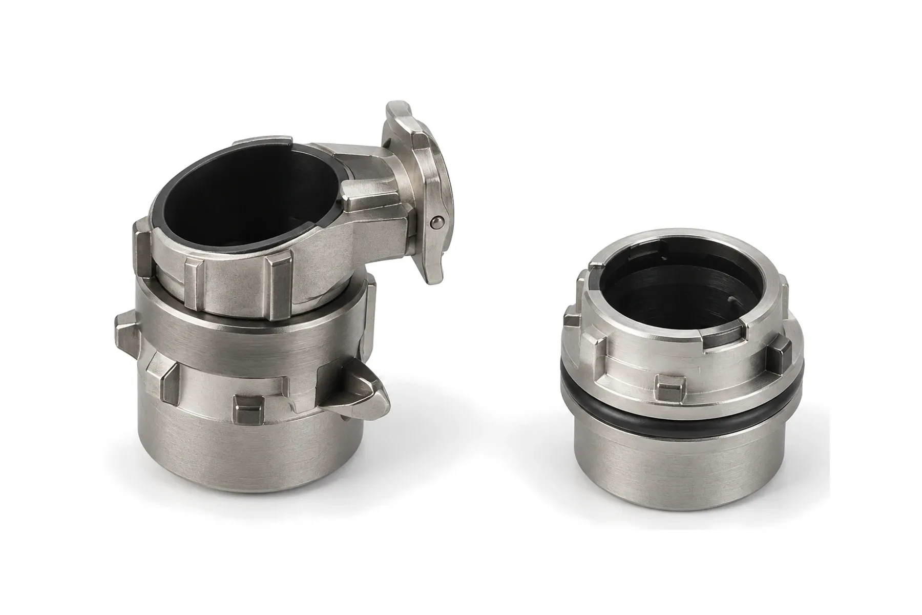
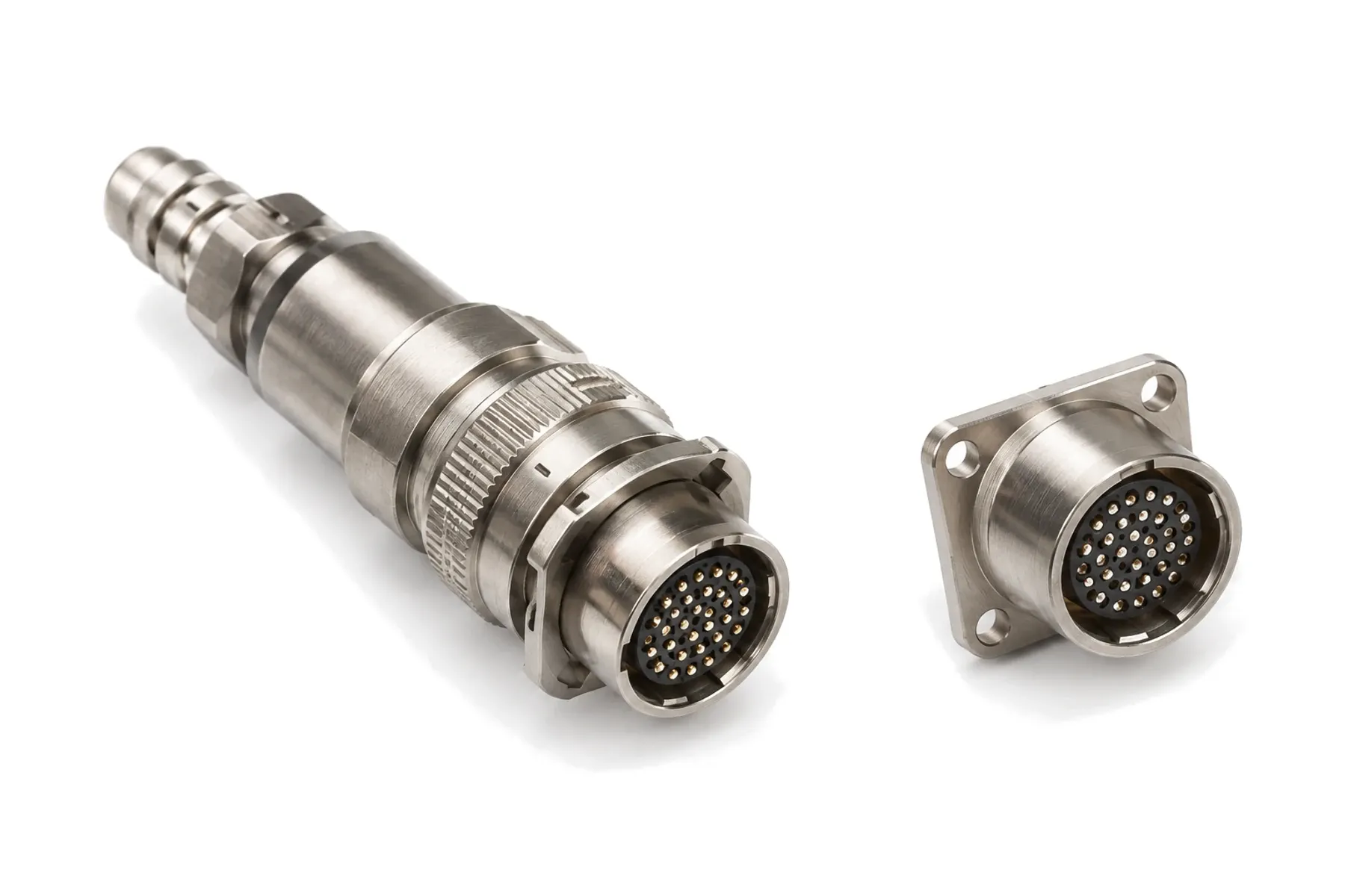
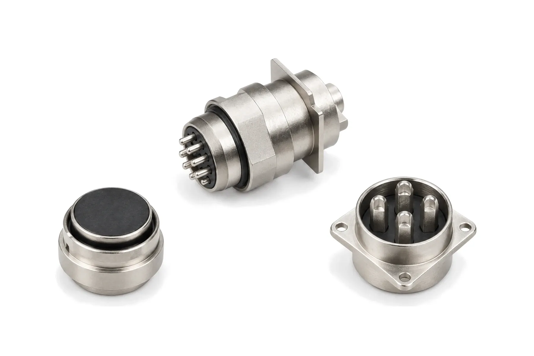
GJB 2889 bayonet · hyperboloid sockets · 1–62 contacts · 5–40 A
XC is a family of bayonet circular connectors built to GJB 2889. Hyperboloid wire-spring sockets give smooth mating and low contact resistance, and the same 32 layouts in shells 14 to 39 are offered with crimp (XC), solder (XCH, CXCH), PCB (XCB), glass-sealed and through-bulkhead contacts. CXCH-01 adds a heavier shell wall, and XCG is a waterproof version that mates with XC.
| Parameter | Value | Condition |
|---|---|---|
| Rated voltage / withstanding voltage | 500 V / 1500 V | Normal atmosphere |
| Rated voltage / withstanding voltage, damp heat | 500 V / 750 V (sealed), 500 V / 1125 V (unsealed) | |
| Rated voltage / withstanding voltage, 1 kPa | 150 V / 300 V (sealed), 250 V / 300 V (unsealed) | |
| Insulation resistance | ≥ 5000 MΩ / ≥ 100 MΩ | Normal / damp heat |
| Shell-to-shell conductivity | ≤ 0.012 Ω (nickel, zinc iridescent), ≤ 0.15 Ω (zinc olive-drab) |
| Parameter | Value | Condition |
|---|---|---|
| Coupling | Bayonet | |
| Durability | 500 mating cycles | |
| Vibration | 10–2000 Hz, 20 g | |
| Shock | 100 g peak | |
| Acceleration | 100 g |
| Parameter | Value | Condition |
|---|---|---|
| Operating temperature | −55 to +150 °C | |
| Relative humidity | Up to 95 % at 40 °C | |
| Altitude | 30,000 m | |
| Leak rate, through-bulkhead receptacle | ≤ 46 Pa·cm³/s | 50.7 kPa differential |
| Leak rate, glass-sealed receptacle | ≤ 0.1 Pa·cm³/s | 152 kPa differential |
| XCG water sealing | 0.3 atm (35.5 kPa) |
| Parameter | Value | Condition |
|---|---|---|
| Shell | High-strength aluminum alloy; steel for glass-sealed receptacles | |
| Insulator | Thermoset plastic; glass for glass-sealed receptacles | |
| Grommet and seals | Silicone rubber | |
| Contacts | Copper alloy, silver or gold plated; crimp contacts rear-release |
GJB 2889 — Chinese specification to which the XC family is built.
Values not listed above — for example vibration level, leak rate or other environmental tests — can be tested to your requirements, including third-party testing. Specifications are subject to change; contact us for the current datasheet.
| Contact | Crimp type | Colour band | Crimp barrel ID (mm) | Wire (mm²) | AWG |
|---|---|---|---|---|---|
| Ø1 | A | Red | 1.0 | 0.20 / 0.35 / 0.50 | 22–20 |
| Ø1 | B | Blue | 1.3 | 0.75 | 20–18 |
| Ø1.5 | A | Red | 1.4 | 0.75 / 1.00 | 18 |
| Ø1.5 | B | Blue | 1.8 | 1.20 / 1.50 | 16–14 |
| Ø2 | A | Red | 2.1 | 2.00 | 14 |
| Ø2 | B | Blue | 2.5 | 2.50 / 3.00 | 12 |
| Ø3 | A | Red | 3.2 | 4.00 | 12 |
| Ø3 | B | Blue | 3.4 | 5.00 | 10 |
| Series code | Version | Notes |
|---|---|---|
| XC | Crimp contacts | |
| XCH | Solder contacts | |
| XCB | PCB solder receptacles | |
| XC-F-M | Glass-sealed square-flange receptacle | |
| XC-S0, S, S1, S2-M | Through-bulkhead sealed receptacles | Pins on one side, sockets on the other |
| CXCH | Solder version derived from XC | Same performance as XCH |
| CXCH-01 | Heavy-wall solder version | Shells 18 to 42; for ships, telecom and machine tools |
| XCG | Waterproof solder version | Sealed to 0.3 atm; mates with XC; Ø4.5 mm 65 A contact available |
| Contact size | Engaging diameter | Contact resistance | Contact resistance (hermetic) | Current rating | Wire size |
|---|---|---|---|---|---|
| Ø1 | 1.0 mm | ≤ 4.5 mΩ | ≤ 9 mΩ (potted) / ≤ 13.5 mΩ (glass-sealed) | 5 A | 0.20–0.75 mm² (AWG 22–18) |
| Ø1.5 | 1.5 mm | ≤ 2.5 mΩ | ≤ 5 mΩ / ≤ 7.5 mΩ | 10 A | 0.75–1.50 mm² (AWG 18–14) |
| Ø2 | 2.0 mm | ≤ 1.25 mΩ | ≤ 2.5 mΩ / ≤ 3.75 mΩ | 20 A | 2.00–3.00 mm² (AWG 14–12) |
| Ø3 | 3.0 mm | ≤ 0.75 mΩ | ≤ 1.5 mΩ / ≤ 2.25 mΩ | 40 A | 4.00–5.00 mm² (AWG 12–10) |
XC [shell][type][contacts][contact type][finish and backshell][key]
Example: XC14F4KD — XC square-flange receptacle, shell 14, 4 socket contacts, shielded, zinc iridescent, key N
| Code segment | Options |
|---|---|
| Series | |
| Shell | |
| Type | |
| Contacts | |
| Contact type | |
| Finish and backshell | |
| Key |
A mated pair is written as receptacle/plug, for example XC14F4KD/P.
Add (B) for B-type crimp contacts for larger wire, for example XC30F30ZD(B).
Cadmium finishes are not RoHS compliant and are supplied on request.
32 standard layouts, viewed from the mating face of the pin insert. The arrangement number is written as shell size – layout (for example 25-35).
32 layouts
| Arrangement | Contacts | Contact sizes |
|---|---|---|
| 14-1 | 1 | 1 × Ø3 |
| 14-2 | 2 | 2 × Ø1.5 |
| 14-3 | 3 | 2 × Ø1, 1 × Ø1.5 |
| 14-4 | 4 | 4 × Ø1 |
| 18-4 | 4 | 2 × Ø1, 2 × Ø3 |
| 18-5 | 5 | 5 × Ø1.5 |
| 18-7 | 7 | 7 × Ø1 |
| 22-10 | 10 | 6 × Ø1, 4 × Ø1.5 |
| 22-14 | 14 | 14 × Ø1 |
| 24-5 | 5 | 5 × Ø3 |
| 24-12 | 12 | 12 × Ø1.5 |
| 24-19 | 19 | 19 × Ø1 |
| 27-12 | 12 | 4 × Ø1, 8 × Ø2 |
| 27-19 | 19 | 14 × Ø1, 5 × Ø1.5 |
| 27-24 | 24 | 24 × Ø1 |
| 30-15 | 15 | 13 × Ø1.5, 2 × Ø2 |
| 30-19 | 19 | 10 × Ø1, 4 × Ø1.5, 3 × Ø2, 2 × Ø3 |
| 30-22 | 22 | 10 × Ø1, 6 × Ø1.5, 6 × Ø2 |
| 30-30 | 30 | 30 × Ø1 |
| 33-22 | 22 | 18 × Ø1.5, 4 × Ø2 |
| 33-27 | 27 | 17 × Ø1, 4 × Ø1.5, 2 × Ø2, 4 × Ø3 |
| 33-41 | 41 | 41 × Ø1 |
| 36-40 | 40 | 34 × Ø1, 4 × Ø1.5, 2 × Ø2 |
| 36-41 | 41 | 31 × Ø1, 10 × Ø1.5 |
| 36-55 | 55 | 55 × Ø1 |
| 39-16 | 16 | 16 × Ø3 |
| 39-35 | 35 | 16 × Ø1, 13 × Ø1.5, 2 × Ø2, 4 × Ø3 |
| 39-36 | 36 | 18 × Ø1, 6 × Ø1.5, 12 × Ø2 |
| 39-46 | 46 | 30 × Ø1, 12 × Ø1.5, 4 × Ø2 |
| 39-47 | 47 | 39 × Ø1, 4 × Ø1.5, 2 × Ø2, 2 × Ø3 |
| 39-51 | 51 | 43 × Ø1, 8 × Ø1.5 |
| 39-62 | 62 | 62 × Ø1 |
They share the same layouts and contacts. XCA is the marine-environment version with stainless-steel options and 240 h acid salt spray testing; XC is the standard family with crimp, solder, PCB and hermetic versions.
Yes — XCG is the waterproof version and mates with XC plugs and receptacles of the same shell and layout.
Part number, drawing, pin-out or a short description of your application.
Our engineers match the configuration and reply with a drawing and quotation.
Samples are made to your order. Third-party testing to your specification is available on request.
You test the samples in your own equipment and approve them.
Production follows the approved sample configuration.
Send your part number, pin-out or drawing. An engineer will reply by email.
38999 Series I type · bayonet coupling · 127 insert arrangements
Bayonet coupling · hyperboloid sockets · 3 to 62 contacts
Bayonet · hyperboloid sockets · 1–62 contacts · 240 h acid salt spray