SHX15 Watertight Threaded Circular Connectors, Stainless Steel
0.5 MPa mated · stainless steel · contacts up to 40 A
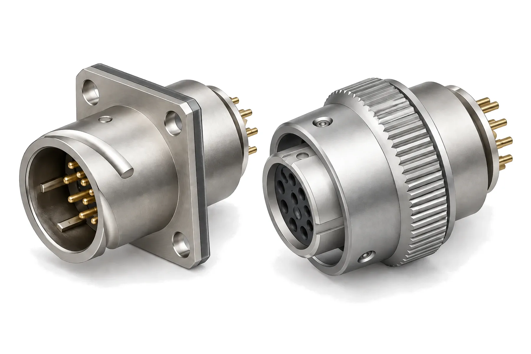
Bayonet coupling · hyperboloid sockets · 3 to 62 contacts
YMG is a bayonet-coupled circular connector for wet, corrosive shipboard environments. Hyperboloid wire-spring sockets give smooth mating and low contact resistance, both halves use solder contacts, and rain-tight sealing protects the interface. Shells are passivated stainless steel, or electroless-nickel copper or aluminum alloy.
| Parameter | Value | Condition |
|---|---|---|
| Rated voltage | 500 V | Room temperature and damp heat |
| Rated voltage | 250 V | Low pressure |
| Withstanding voltage | 1500 V / 1125 V / 300 V | Room temperature / damp heat / low pressure |
| Insulation resistance | ≥ 5000 MΩ / ≥ 100 MΩ | Room temperature / damp heat |
| EMI shielding | ≥ 45 dB | 100 MHz to 1 GHz |
| Parameter | Value | Condition |
|---|---|---|
| Coupling | Bayonet | |
| Durability | 1000 mating cycles | |
| Vibration | 10–2000 Hz, 196 m/s² | |
| Shock | 980 m/s² | |
| Acceleration | 980 m/s² | |
| Operating temperature | −55 to +200 °C | |
| Humidity | 95 % RH at 60 °C | |
| Sealing | Rain-tight | Not for immersion |
| Materials | Thermoset insulator; silicone rubber seals; gold-plated copper-alloy contacts |
Values not listed above — for example vibration level, leak rate or other environmental tests — can be tested to your requirements, including third-party testing. Specifications are subject to change; contact us for the current datasheet.
| Series code | Version | Notes |
|---|---|---|
| YMG…T | Plug | |
| YMG…F | Square-flange receptacle | P: rear thread for backshell; D: no rear thread |
| YMGB…F / …N | PCB receptacles, square flange or jam nut | |
| YMG-AP, -AP01, -GP | Straight and 90° backshells | Cable clamp, 360° shielding, O-ring seal to connector |
| YMG…B / …C | Rain-tight sealing caps for receptacle / plug |
| Code | Shell material | Finish | Shell conductivity | EMI shielding | Temperature | Salt spray |
|---|---|---|---|---|---|---|
| 1 | Aluminum alloy | Electroless nickel | — | ≥ 45 dB, 100 MHz–1 GHz | −55 to +200 °C | 48 h |
| 11 | Copper alloy | Electroless nickel | — | ≥ 45 dB, 100 MHz–1 GHz | −55 to +200 °C | 500 h |
| 40 | Stainless steel | Passivated | — | ≥ 45 dB, 100 MHz–1 GHz | −55 to +200 °C | 1000 h |
| Contact size | Engaging diameter | Contact resistance | Current rating | Wire size |
|---|---|---|---|---|
| Ø0.635 | 0.635 mm | ≤ 25 mΩ | 3 A | Solder cup Ø0.7 mm |
| Ø1.0 | 1.0 mm | ≤ 4.5 mΩ | 5 A | Solder cup Ø1.2 mm |
| Ø1.5 | 1.5 mm | ≤ 2.5 mΩ | 10 A | Solder cup Ø1.7 mm |
| Ø2.0 | 2.0 mm | ≤ 1.25 mΩ | 20 A | Solder cup Ø2.6 mm |
| Ø3.0 | 3.0 mm | ≤ 0.75 mΩ | 40 A | Solder cup Ø3 mm |
| Ø3.5 | 3.5 mm | ≤ 0.7 mΩ | 50 A | Solder cup Ø4.8 mm |
YMG [shell] [type] [contacts] [contact type] [rear] [finish] [key] [-option]
Example: YMG16T3K1P40 — Plug, shell 16, 3 gold-plated socket contacts, rear thread for backshell, passivated stainless steel, key position N
| Code segment | Options |
|---|---|
| Shell | |
| Type | |
| Contacts | |
| Contact type | |
| Rear | |
| Finish | |
| Key | |
| Option |
Receptacle example: YMG16F3Z1P40W-08 — square-flange receptacle, shell 16, 3 gold-plated pins, rear thread, stainless steel, key W, shielded flange gasket.
56 standard layouts, viewed from the mating face of the pin insert. The arrangement number is written as shell size – layout (for example 25-35).
56 layouts
| Arrangement | Contacts | Contact sizes |
|---|---|---|
| 16-3 | 3 | 3 × Ø1.5 mm |
| 16-4 | 4 | 4 × Ø1.0 mm |
| 16-7 | 7 | 7 × Ø1.0 mm |
| 16-4-1 | 4 | 2 × Ø1.0 mm, 2 × Ø1.5 mm |
| 16-10 | 10 | 10 × Ø0.635 mm |
| 18-3 | 3 | 3 × Ø3.0 mm |
| 18-4 | 4 | 4 × Ø1.5 mm |
| 18-7 | 7 | 7 × Ø1.0 mm |
| 20-7 | 7 | 7 × Ø1.5 mm |
| 20-10 | 10 | 10 × Ø1.0 mm |
| 20-10-1 | 10 | 6 × Ø1.0 mm, 4 × Ø1.5 mm |
| 20-11 | 11 | 11 × Ø1.0 mm |
| 22-10 | 10 | 10 × Ø1.0 mm |
| 22-4 | 4 | 4 × Ø3.0 mm |
| 24-3 | 3 | 3 × Ø3.0 mm |
| 24-4 | 4 | 4 × Ø3.0 mm |
| 24-5 | 5 | 5 × Ø3.0 mm |
| 24-8 | 8 | 4 × Ø1.0 mm, 4 × Ø3.0 mm |
| 24-10 | 10 | 10 × Ø1.5 mm |
| 24-12 | 12 | 12 × Ø1.5 mm |
| 24-14 | 14 | 14 × Ø1.0 mm |
| 24-19 | 19 | 19 × Ø1.0 mm |
| 27-14 | 14 | 14 × Ø1.5 mm |
| 27-14-1 | 14 | 6 × Ø1.0 mm, 8 × Ø2.0 mm |
| 27-19 | 19 | 14 × Ø1.0 mm, 5 × Ø1.5 mm |
| 27-19-1 | 19 | 19 × Ø1.0 mm |
| 27-26 | 26 | 26 × Ø1.0 mm |
| 27-4 | 4 | 4 × Ø3.5 mm |
| 27-12 | 12 | 8 × Ø1.0 mm, 4 × Ø3.0 mm |
| 30-12 | 12 | 4 × Ø1.5 mm, 8 × Ø2.0 mm |
| 30-15 | 15 | 13 × Ø1.5 mm, 2 × Ø2.0 mm |
| 30-19 | 19 | 10 × Ø1.0 mm, 4 × Ø1.5 mm, 3 × Ø2.0 mm, 2 × Ø3.0 mm |
| 30-22 | 22 | 10 × Ø1.0 mm, 6 × Ø1.5 mm, 6 × Ø2.0 mm |
| 30-24 | 24 | 24 × Ø1.0 mm |
| 30-30 | 30 | 30 × Ø1.0 mm |
| 30-32 | 32 | 32 × Ø1.0 mm |
| 30-12-1 | 12 | 12 × Ø2.0 mm |
| 33-22 | 22 | 18 × Ø1.5 mm, 4 × Ø2.0 mm |
| 33-24 | 24 | 24 × Ø1.5 mm |
| 33-27 | 27 | 17 × Ø1.0 mm, 4 × Ø1.5 mm, 2 × Ø2.0 mm, 4 × Ø3.0 mm |
| 33-30 | 30 | 30 × Ø1.0 mm |
| 33-35 | 35 | 35 × Ø1.0 mm |
| 36-37 | 37 | 37 × Ø1.0 mm |
| 36-40 | 40 | 34 × Ø1.0 mm, 4 × Ø1.5 mm, 2 × Ø2.0 mm |
| 36-41 | 41 | 31 × Ø1.0 mm, 10 × Ø1.5 mm |
| 36-55 | 55 | 55 × Ø1.0 mm |
| 36-17 | 17 | 7 × Ø1.5 mm, 4 × Ø3.0 mm, 6 × Ø3.5 mm |
| 39-16 | 16 | 16 × Ø3.0 mm |
| 39-35 | 35 | 16 × Ø1.0 mm, 13 × Ø1.5 mm, 2 × Ø2.0 mm, 4 × Ø3.0 mm |
| 39-36 | 36 | 18 × Ø1.0 mm, 6 × Ø1.5 mm, 12 × Ø2.0 mm |
| 39-37 | 37 | 37 × Ø1.5 mm |
| 39-47 | 47 | 39 × Ø1.0 mm, 4 × Ø1.5 mm, 2 × Ø2.0 mm, 2 × Ø3.0 mm |
| 39-48 | 48 | 32 × Ø1.0 mm, 12 × Ø1.5 mm, 4 × Ø2.0 mm |
| 39-51 | 51 | 43 × Ø1.0 mm, 8 × Ø1.5 mm |
| 39-55 | 55 | 55 × Ø1.0 mm |
| 39-62 | 62 | 62 × Ø1.0 mm |
YMG is rain-tight: sealed against rain, spray and humidity, but not intended for immersion, even short-term. For immersion, choose SHX15 or SHX16 (watertight to 0.5 MPa when mated), or the 7000 m rated SHX33/34/35.
A socket made of fine spring wires set at an angle, forming a hyperboloid. It gives smooth mating, low contact resistance and stable contact under vibration.
Passivated stainless steel (40) for the most corrosive locations (1000 h salt spray), nickel-plated copper alloy (11, 500 h) or aluminum alloy (1, 48 h) where weight matters.
Part number, drawing, pin-out or a short description of your application.
Our engineers match the configuration and reply with a drawing and quotation.
Samples are made to your order. Third-party testing to your specification is available on request.
You test the samples in your own equipment and approve them.
Production follows the approved sample configuration.
Send your part number, pin-out or drawing. An engineer will reply by email.
0.5 MPa mated · stainless steel · contacts up to 40 A
38999 type · 0.5 MPa mated · 126 insert arrangements