J599 Series III Circular Connectors (38999 Series III Type)
38999 Series III type · shell sizes 9–25 · 184 insert arrangements
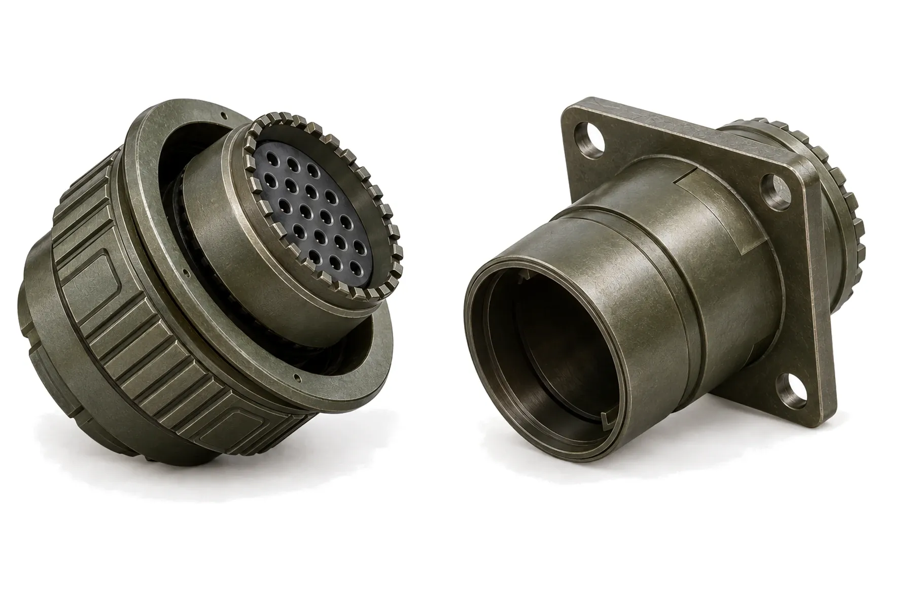
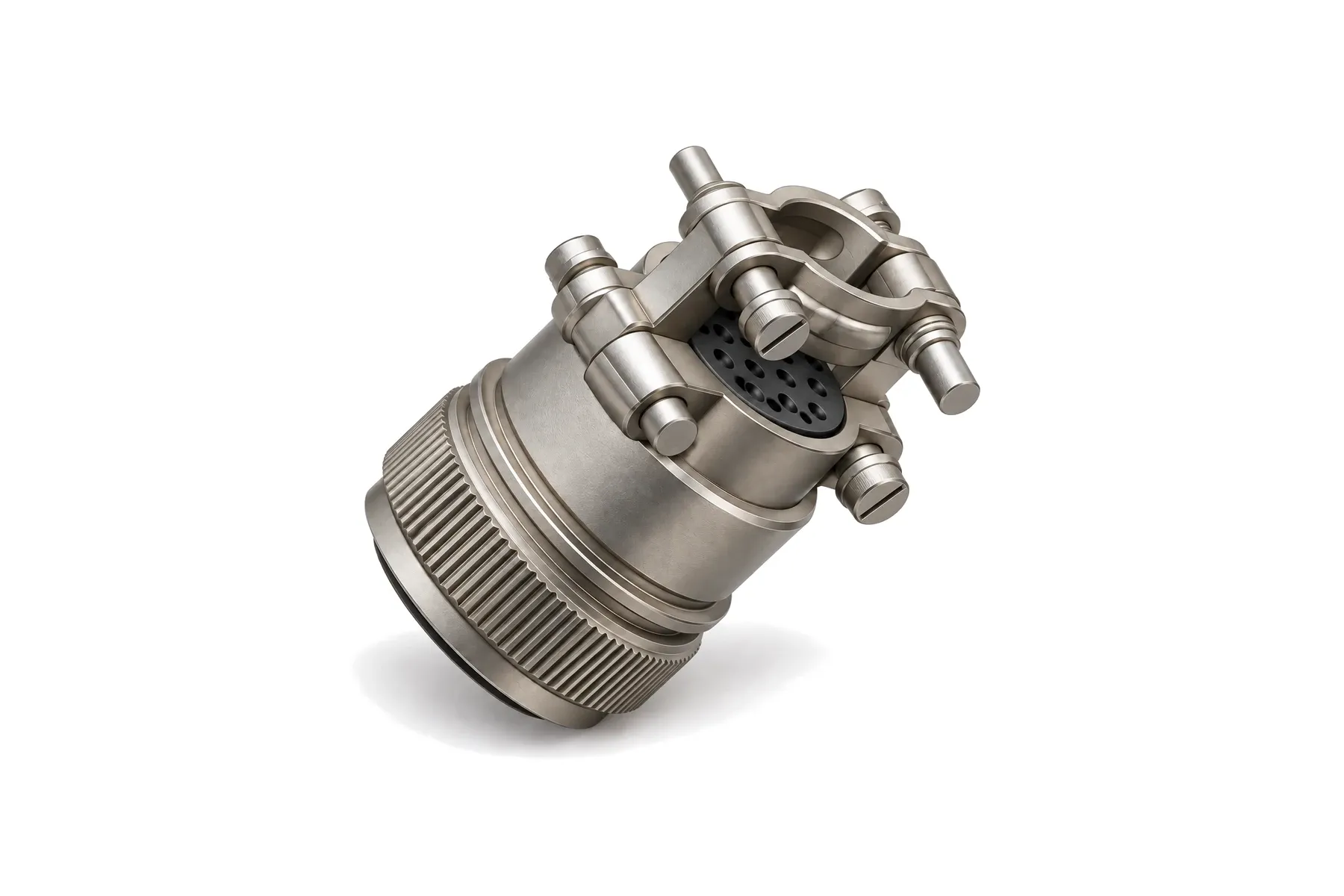
IP67 with J1784FS backshell · threaded 38999 type · rain-tested
J599FS adds a seal at the mating face of our Series III-type connector so that water cannot collect in the five key slots. Paired with a J1784FS waterproof backshell, which seals each wire with a double pressure plate, the complete connector reaches IP67. It keeps the triple-start threaded coupling, anti-decoupling and EMI shielding of the 38999 Series III type.
| Parameter | Value | Condition |
|---|---|---|
| Ingress protection | IP67 | Mated, with J1784FS backshells |
| Rain (drip) test | 1.7 mm/min, wind 18 m/s | GJB 150.8A-2009 |
| Insulation resistance after water immersion | ≥ 20 MΩ | |
| Hermetic receptacle leak rate | ≤ 1 × 10⁻⁸ Pa·m³/s | 0.1 MPa pressure differential |
| Parameter | Value | Condition |
|---|---|---|
| Dielectric withstanding voltage, service rating M | 1300 Vrms / 800 Vrms | Sea level / 21,000 m altitude, mated |
| Dielectric withstanding voltage, service rating N | 1000 Vrms / 600 Vrms | Sea level / 21,000 m altitude, mated |
| Dielectric withstanding voltage, service rating I | 1800 Vrms / 1000 Vrms | Sea level / 21,000 m altitude, mated |
| Dielectric withstanding voltage, service rating II | 2300 Vrms / 1000 Vrms | Sea level / 21,000 m altitude, mated |
| Insulation resistance | ≥ 5000 MΩ | Room temperature |
| Insulation resistance | ≥ 1000 MΩ (non-hermetic) / ≥ 200 MΩ (hermetic) | High temperature |
| Parameter | Value | Condition |
|---|---|---|
| Durability | 500 mating cycles | |
| Shock | 2940 m/s² | |
| Sine vibration | 10–2000 Hz, 60 g (140–2000 Hz), 3 × 12 h | With temperature cycling |
| Random vibration | 50–2000 Hz, 1 g²/Hz (100–2000 Hz), 2 × 8 h | At maximum temperature |
| Random vibration | 25–2000 Hz, 5 g²/Hz (100–300 Hz), 2 × 8 h | |
| Damp heat | 10 cycles × 24 h | |
| Operating temperature | −65 to +200 °C | −65 to +175 °C for cadmium finish |
| Operating altitude | ≤ 30,480 m |
GJB 599B (Series III type) — Base design; J599FS adds the mating-face seal. GJB 1784 — Base design of the J1784FS backshells.
Values not listed above — for example vibration level, leak rate or other environmental tests — can be tested to your requirements, including third-party testing. Specifications are subject to change; contact us for the current datasheet.
Weight in grams, socket / pin version.
| Shell | Arrangement | Receptacle, stainless | Plug, stainless | Receptacle, aluminum | Plug, aluminum |
|---|---|---|---|---|---|
| 9 (A) | 44 | 28.6 / 26.7 | 35.8 / 33.9 | 18.6 / 16.7 | 25.8 / 23.9 |
| 11 (B) | 06 | 41.3 / 34.4 | 48.6 / 42.7 | 31.3 / 24.4 | 38.6 / 32.7 |
| 13 (C) | 13 | 56.3 / 45.3 | 75.2 / 66.2 | 46.3 / 35.3 | 60.2 / 51.2 |
| 15 (D) | 22 | 70.1 / 54.7 | 90.8 / 78.5 | 55.1 / 39.7 | 70.8 / 58.5 |
| 17 (E) | 37 | 95.3 / 75.5 | 100.2 / 85.5 | 80.3 / 60.5 | 75.2 / 60.5 |
| 19 (F) | 42 | 103.2 / 78.9 | 138.1 / 103.8 | 83.2 / 88.9 | 108.1 / 73.8 |
| 21 (G) | 55 | 125.7 / 94.6 | 142.7 / 114.6 | 100.7 / 70.6 | 112.7 / 84.6 |
| 23 (H) | 66 | 145.8 / 106.7 | 165.2 / 128.1 | 115.8 / 76.7 | 135.2 / 93.1 |
| 25 (J) | 79 | 165.3 / 120.7 | 185.6 / 141.5 | 125.3 / 80.7 | 145.6 / 101.5 |
Stainless steel K and S weigh the same; aluminum W and F weigh the same.
| Series code | Version | Notes |
|---|---|---|
| J599FS/20 | Square-flange receptacle | |
| J599FS/26 | Plug | |
| J1784FS/38, /39 | Waterproof cable-clamp backshell, straight / 90° | For J599 connectors; metric M12 × 1 to M37 × 1 thread; finishes to match the connector |
| J1784FS/88, /90 | Waterproof shielded backshell, straight / 90° | For J599 connectors; optional band ring for 360° shield termination |
| J1784FS/49, /47 | Waterproof cable-clamp backshell, straight / 90° | For JY27 (Series I and II) connectors; UNEF thread |
| J1784FS/85, /87 | Waterproof shielded backshell, straight / 90° | For JY27 (Series I and II) connectors |
| Code | Shell material | Finish | Shell conductivity | EMI shielding | Temperature | Salt spray |
|---|---|---|---|---|---|---|
| W (B) | Aluminum alloy | Olive-drab cadmium | 2.5 mΩ | 50 dB at 10 GHz | −65 to +175 °C | 500 h |
| F | Aluminum alloy | Nickel | 1 mΩ | 50 dB at 10 GHz | −65 to +200 °C | 96 h |
| K | Stainless steel | Passivated | 50 mΩ | — | −65 to +200 °C | 500 h |
| S | Stainless steel | Nickel | 1 mΩ | — | −65 to +200 °C | 500 h |
| TA | Titanium alloy | None | 10 mΩ | 65 dB at 10 GHz | −65 to +200 °C | 500 h |
| Contact size | Engaging diameter | Contact resistance | Contact resistance (hermetic) | Current rating | Wire size |
|---|---|---|---|---|---|
| 22D | 0.76 mm | ≤ 14.6 mΩ | ≤ 28 mΩ | 5 A | AWG 22–26 (0.13–0.33 mm²) |
| 20 | 1.02 mm | ≤ 7.3 mΩ | ≤ 12.0 mΩ | 7.5 A | AWG 20–24 (0.20–0.52 mm²) |
| 16 | 1.58 mm | ≤ 3.7 mΩ | ≤ 8.5 mΩ | 13 A | AWG 16–20 (0.52–1.31 mm²) |
| 12 | 2.41 mm | ≤ 1.83 mΩ | ≤ 5 mΩ | 23 A | AWG 12–14 (2.08–3.31 mm²) |
J599FS/ [type] H [finish] [shell] [arrangement] [contact] [key] [suffix] -[lockwire]
Example: J599FS/20HWB06PNR2-S — Square-flange receptacle, olive-drab cadmium, shell B (size 11), arrangement 11-06, pin contacts, key N, two pairs of thermocouple contacts, lockwire version with M3 × 12 screws
| Code segment | Options |
|---|---|
| Type | |
| H | |
| Finish | |
| Shell | |
| Arrangement | |
| Contact | |
| Key | |
| Suffix | |
| Lockwire |
Backshell example: J1784FS/88-HW1522S01 — straight shielded backshell for J599, olive-drab cadmium, shell 15, arrangement 15-22, socket side, wire range 01. Wire range 01 or 02 is chosen from your wire insulation diameter (Ø 1.04–3.63 mm across all sizes).
32 standard layouts, viewed from the mating face of the pin insert. The arrangement number is written as shell size – layout (for example 25-35). The service rating sets the withstanding voltage (see specifications).
32 layouts
| Arrangement | Contacts | Contact sizes | Service rating |
|---|---|---|---|
| 9-03 | 3 | 3 × size 20 | I |
| 9-44 | 4 | 4 × size 22D | M |
| 9-98 | 3 | 3 × size 20 | I |
| 11-02 | 2 | 2 × size 16 | I |
| 11-04 | 4 | 4 × size 20 | I |
| 11-05 | 5 | 5 × size 20 | I |
| 11-06 | 6 | 6 × size 22D | M |
| 13-03 | 3 | 3 × size 16 | II |
| 13-08 | 8 | 8 × size 20 | I |
| 13-13 | 13 | 13 × size 22D | M |
| 15-04A | 4 | 4 × size 12 | M |
| 15-05 | 5 | 5 × size 16 | II |
| 15-06A | 6 | 6 × size 16 | M |
| 15-18 | 18 | 18 × size 20 | I |
| 15-22 | 22 | 22 × size 22D | M |
| 17-08 | 8 | 8 × size 16 | II |
| 17-26 | 26 | 26 × size 20 | I |
| 17-37 | 37 | 37 × size 22D | M |
| 19-11 | 11 | 11 × size 16 | II |
| 19-32 | 32 | 32 × size 20 | I |
| 19-42 | 42 | 42 × size 22D | M |
| 21-16 | 16 | 16 × size 16 | II |
| 21-24 | 24 | 24 × size 20 | I |
| 21-25 | 25 | 25 × size 20 | I |
| 21-27 | 27 | 27 × size 20 | I |
| 21-55 | 55 | 55 × size 22D | I |
| 23-99 | 11 | 11 × size 16 | II |
| 23-32 | 32 | 32 × size 20 | I |
| 23-66 | 66 | 66 × size 22D | M |
| 25-29 | 29 | 29 × size 16 | I |
| 25-61 | 61 | 61 × size 20 | I |
| 25-79 | 79 | 79 × size 22D | I |
The IP67 rating applies to the complete connector: J599FS plug and receptacle mated, with J1784FS waterproof backshells sealing the wire entry. Standard backshells do not seal each wire.
A standard connector can hold water in the key slots at the mating face. J599FS adds a seal there, and the J1784FS backshell seals each wire with a double pressure plate.
Yes. The listed layouts are standard; other layouts can be added to your requirements.
Part number, drawing, pin-out or a short description of your application.
Our engineers match the configuration and reply with a drawing and quotation.
Samples are made to your order. Third-party testing to your specification is available on request.
You test the samples in your own equipment and approve them.
Production follows the approved sample configuration.
Send your part number, pin-out or drawing. An engineer will reply by email.
38999 Series III type · shell sizes 9–25 · 184 insert arrangements
Cadmium-free nickel-PTFE finish · marine-grade · up to 5000 mating cycles