J599HV High-Voltage, High-Current Circular Connectors, up to 300 A
Up to 300 A · 3500 V withstanding · IP65 · HV interlock option
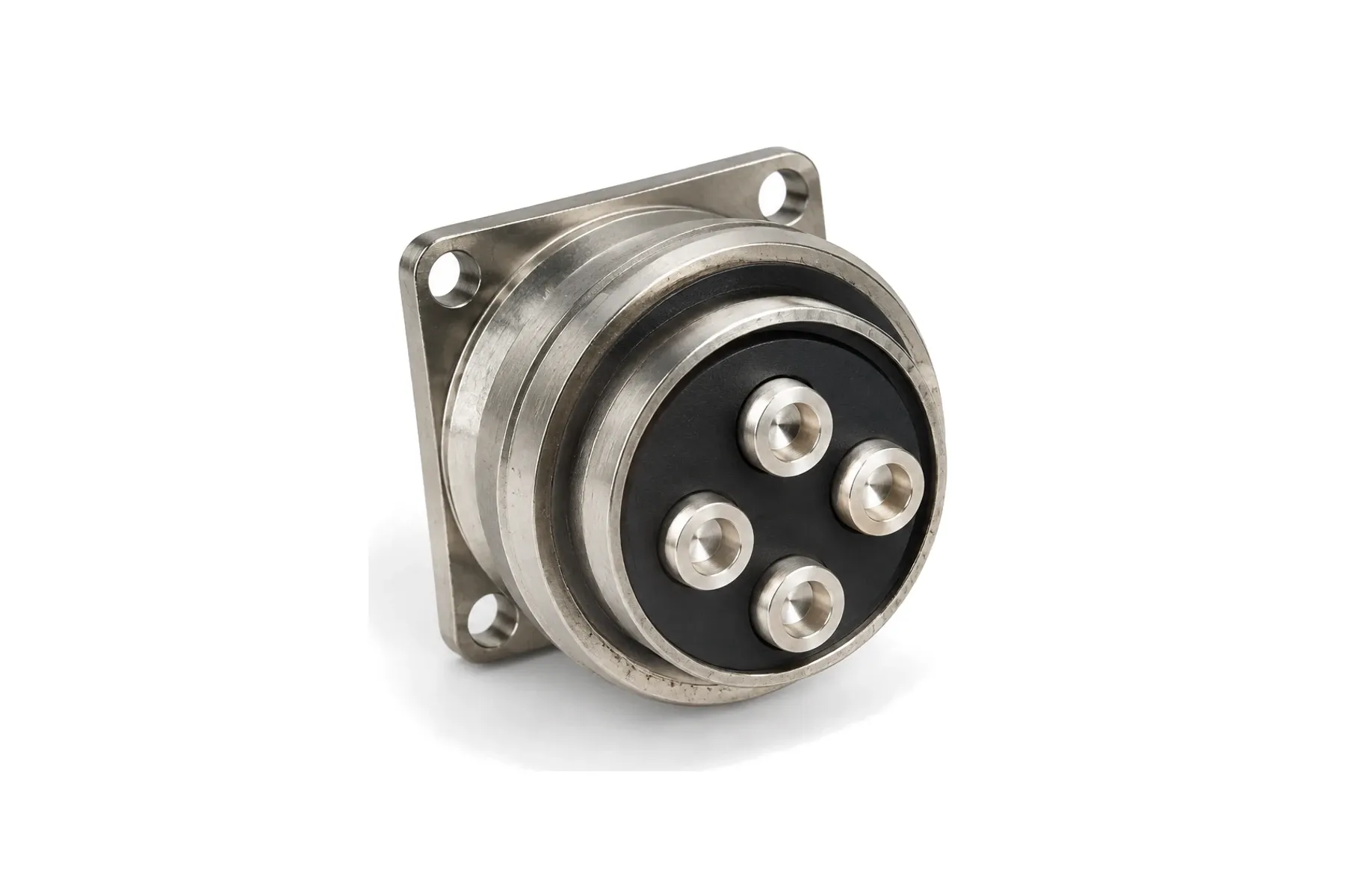
Power only · 25–300 A per contact · hyperboloid sockets · bayonet
XCD is a bayonet circular connector made only for power. Hyperboloid wire-spring sockets from Ø2.5 to Ø14 mm carry 25 to 300 A each, in 17 layouts from one to eight contacts. Plugs, square-flange and jam-nut receptacles are available with solder, crimp or threaded (bolted) cable connection, and pins or sockets can be fitted on either side.
| Parameter | Value | Condition |
|---|---|---|
| Rated voltage / withstanding voltage | 500 V / 1500 V | Normal atmosphere |
| Rated voltage / withstanding voltage, damp heat | 500 V / 1125 V | |
| Insulation resistance | ≥ 5000 MΩ / ≥ 1000 MΩ | Normal / damp heat |
| Shell-to-shell conductivity | ≤ 0.012 Ω (nickel), ≤ 0.15 Ω (zinc olive-drab) |
| Parameter | Value | Condition |
|---|---|---|
| Coupling | Bayonet | |
| Durability | 500 mating cycles | |
| Vibration | 10–2000 Hz, 196 m/s² (20 g) | |
| Shock | 980 m/s² (100 g) | |
| Acceleration | 980 m/s² (100 g) |
| Parameter | Value | Condition |
|---|---|---|
| Operating temperature | −55 to +150 °C | |
| Relative humidity | Up to 95 % at 40 °C | |
| Altitude | 30,000 m |
| Parameter | Value | Condition |
|---|---|---|
| Shell | High-strength aluminum alloy, electroless nickel | |
| Insulator | Thermoset plastic | |
| Contacts | Copper alloy, gold plated |
Values not listed above — for example vibration level, leak rate or other environmental tests — can be tested to your requirements, including third-party testing. Specifications are subject to change; contact us for the current datasheet.
| Contact | Solder cup or crimp barrel ID (mm) | Outside diameter (mm) | Length out of shell (mm) |
|---|---|---|---|
| Ø1.5 | 2.0 | 2.5 | 6.2 |
| Ø2.0 | 2.5 | 3.1 | 3.5 |
| Ø2.5 | 2.5 | 3.1 | 6.2 |
| Ø3.5 | 4.8 | 5.8 | 6.2 |
| Ø4.5 | 5.5 | 6.5 | 8.0 |
| Ø5.5 | 6.5 | 7.5 | 10.0 |
| Ø7.5 | 9.0 | 10.5 | 10.5 |
| Ø9.0 crimp | 12.0 | 17.0 | — |
| Ø10.0 | 10.0 | 12.0 | 10.0 |
| Ø12.0 crimp | 15.0 | 20.0 | — |
| Series code | Version | Notes |
|---|---|---|
| XCD…T | Plug | |
| XCD…F | Square-flange receptacle | With or without rear thread |
| XCD…L | Jam-nut receptacle | |
| Type I / Type II | Solder or crimp cable connection / threaded (bolted) cable connection |
| Contact size | Engaging diameter | Contact resistance | Current rating | Wire size |
|---|---|---|---|---|
| Ø2.5 | 2.5 mm | ≤ 1.00 mΩ | 25 A | — |
| Ø3.5 | 3.5 mm | ≤ 0.50 mΩ | 50 A | — |
| Ø4.5 | 4.5 mm | ≤ 0.35 mΩ | 60 A | — |
| Ø5.5 | 5.5 mm | ≤ 0.30 mΩ | 100 A | — |
| Ø7.5 | 7.5 mm | ≤ 0.20 mΩ | 150 A | — |
| Ø9.0 | 9.0 mm | ≤ 0.17 mΩ | 200 A | — |
| Ø10 | 10 mm | ≤ 0.20 mΩ | 200 A | — |
| Ø12 | 12 mm | ≤ 0.15 mΩ | 250 A | — |
| Ø14 | 14 mm | ≤ 0.12 mΩ | 300 A | — |
XCD [shell][type][layout][contact][finish][key]
Example: XCD36T4K1P1(W) — Plug, shell 36, layout 36-4 (4 × Ø4.5 mm), gold-plated sockets, nickel with rear thread, key W
| Code segment | Options |
|---|---|
| Shell | |
| Type | |
| Layout | |
| Contact | |
| Finish | |
| Key |
Contacts Ø1.0 to Ø3.0 mm in mixed layouts have the ratings of the XC series (5 to 40 A).
16 standard layouts, viewed from the mating face of the pin insert. The arrangement number is written as shell size – layout (for example 25-35).
16 layouts
| Arrangement | Contacts | Contact sizes |
|---|---|---|
| 22-1 | 1 | 1 × Ø10 |
| 22-3 | 3 | 3 × Ø3 |
| 22-4 | 4 | 4 × Ø3 |
| 27-1 | 1 | 1 × Ø12 |
| 27-6 | 6 | 4 × Ø1.5, 2 × Ø3.5 |
| 33-9 | 9 | 5 × Ø2.5, 4 × Ø3.5 |
| 36-2 | 2 | 2 × Ø10 |
| 36-3 | 3 | 3 × Ø4.5 |
| 36-4 | 4 | 4 × Ø4.5 |
| 36-6 | 6 | 5 × Ø2.0, 1 × Ø10 |
| 39-3 | 3 | 3 × Ø10 |
| 39-4 | 4 | 4 × Ø5.5 |
| 45-1 | 1 | 1 × Ø14 |
| 45-4 | 4 | 4 × Ø7.5 |
| 45-8 | 8 | 4 × Ø1.0, 4 × Ø7.5 |
| 85-4 | 4 | 1 × Ø9.0, 3 × Ø12 |
Each contact carries 25 A (Ø2.5 mm) up to 300 A (Ø14 mm). The 85-4 layout combines one Ø9 mm and three Ø12 mm contacts for three-phase power with a neutral or earth.
Yes — the Type II versions connect the cable with a threaded stud. Tell us the cable size and we will propose the terminal.
Part number, drawing, pin-out or a short description of your application.
Our engineers match the configuration and reply with a drawing and quotation.
Samples are made to your order. Third-party testing to your specification is available on request.
You test the samples in your own equipment and approve them.
Production follows the approved sample configuration.
Send your part number, pin-out or drawing. An engineer will reply by email.
Up to 300 A · 3500 V withstanding · IP65 · HV interlock option
33–225 A · 38999 Series III shell · marine grade
5–800 A per contact · 400 V · 30 layouts · hermetic bulkhead version
GJB 2889 bayonet · hyperboloid sockets · 1–62 contacts · 5–40 A